
Automatic 12 Volt Lamp Fader
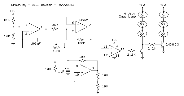
The circuit operates by utilizing an LM324 quad op-amp, which is versatile and can function in various configurations. The first op-amp is configured as a Schmitt trigger oscillator to generate a high-frequency square wave at about 75 Hz. This square wave is essential for creating the rapid on-off cycling needed for the fading effect. The second and third op-amps generate a lower frequency ramp signal that controls the fading rate of the lamps. These ramp signals are linear and can be adjusted based on the desired fading speed by altering component values in the circuit.
The fourth op-amp compares the two ramp signals, producing a rectangular waveform whose duty cycle varies based on the input from the ramp signals. This varying duty cycle is crucial as it determines how long the output is high versus low, effectively controlling the brightness of the lamps. The output from this op-amp drives a transistor, specifically the 2N3053, which acts as a switch to control the power supplied to the lamps.
In the case of higher power applications, such as automotive lighting, the 2N3053 may not suffice due to its current limitations. Therefore, a suitable MOSFET should be selected that can handle the required current load. The circuit also includes provisions for inverting the output signal to create a complementary fading effect between two groups of lamps, enhancing the visual impact of the design.
For implementation, careful consideration should be given to the resistor values used in series with the LEDs or lamps to ensure they operate within safe current limits. The use of a 220-ohm resistor for each group of four LEDs is a good starting point, but adjustments may be necessary based on the specific characteristics of the LEDs or lamps being used. Additionally, the schematic should be followed meticulously to ensure all connections are correct, particularly when integrating different types of lighting components.This circuit is similar to the "Fading Red Eyes" circuit (in the LED section) used to fade a pair of red LEDs. In this version, the lamps are faded by varying the duty cycle so that higher power incandescent lamps can be used without much power loss.
The switching waveform is generated by comparing two linear ramps of different frequencies. The hi gher frequency ramp waveform (about 75 Hz. ) is produced from one section of the LM324 quad op-amp wired as a Schmitt trigger oscillator. The lower frequency ramp controls the fading rate and is generated from the upper two op-amps similar to the "fading eyes" circuit. The two ramp waveforms at pins 9 and 1 are compared by the 4th op-amp which generates a varying duty cycle rectangular waveform to drive the output transistor.
A second transistor is used to invert the waveform so that one group of lamps will fade as the other group brightens. The 2N3053 will handle up to 500 milliamps so you could connect 12 strings of 4 LEDs each (48 LEDs) with a 220 ohm resistor in series with each group of 4 LEDs.
This would total about 250 milliamps. Or you can use three 4 volt, 200 mA Xmas tree bulbs in series. For higher power 12 volt automobile lamps, the transistor will need to be replaced with a MOSFET that can handle several amps of current. See the drawing below the schematic for possible hookups. 🔗 External reference
Related Circuits
This circuit is designed to demonstrate high-frequency high voltage, capable of producing voltages up to approximately 30 kV, depending on the transformer used. It is economical and straightforward to construct, primarily utilizing a standard TV flyback transformer. The circuit...
Figure 1-22 (a) illustrates a circuit that converts an input voltage of 0 to +10V (Ui) into a pulse with an output frequency ranging from 0 to 100kHz. In this configuration, pin 7 of the VFC320 is connected to...

In some cases, it is necessary to power a circuit from a battery, where the required supply voltage falls within the battery's discharge curve. A new battery provides a higher voltage than needed, while a battery nearing the end...

MSP430 microcontroller and I2C-compatible slave peripheral device. Temperature measurement tasks can be accomplished in a variety of ways. The MSP430 microcontroller is a low-power, 16-bit device widely used in embedded systems, particularly for applications requiring efficient power management and precise...

The circuit detailed in this document is designed to produce up to 30 kilovolts or more from a low-voltage DC source using a flyback transformer (LOPT) salvaged from a black-and-white or color television or computer monitor. With a typical...

This is a circuit design for a digital voltmeter with an LED display. It is suitable for measuring the output voltage of a DC power supply. The circuit features a 3.5-digit LED display with a negative voltage indicator and...