
Automatic Dual Output Display
The circuit utilizes a combination of digital logic components to achieve the desired sequential lighting effect. The oscillator formed by gates N1 and N2 generates a square wave signal, which serves as the clock input for the BCD counter (IC2). The CD4510 counter is capable of counting in both directions, which is vital for the operation of this circuit. The active low pulse generated at pin 7 during the terminal counts serves as a control signal for the subsequent operations of the decade counter (IC3).
The decade counter CD4017 is configured as a toggle flip-flop, allowing it to switch states based on the terminal count signals it receives from IC2. The feedback from the Q2 output to the reset pin ensures that the counter toggles its output state correctly, facilitating the alternating high and low states at pin 3. This output is crucial for controlling the sequence of bulb illumination.
The 1-of-10 decoder (IC4) plays a critical role in driving the triacs, which are used to control the power to each bulb. As the BCD counter counts up, the decoder activates each output in sequence, lighting each bulb in order. This sequence is reversed during the count-down operation, providing a dynamic visual display. The use of triacs allows for efficient control of the AC power supplied to the bulbs, ensuring safe operation while achieving the desired lighting effects.
Overall, this circuit exemplifies the integration of digital logic and power control components to create an engaging visual experience through sequential lighting. The design is suitable for various applications, including decorative lighting and visual displays.This circuit lights up ten bulbs sequentially, first in one direc- tion and then in the opposite direction, thus presenting a nice visual effect. In this circuit, gates N1 and N2 form an oscillator. The output of this oscillator is used as a clock for BCD up/down counter CD4510 (IC2). Depending on the logic state at its pin 10, the counter counts up or down. During count up operation, pin 7 of IC2 outputs an active low pulse on reaching the ninth count. Similarly, during count-down operation, you again get a low-going pulse at pin 7. This terminal count output from pin 7, after inversion by gate N3, is connected to clock pin 14 of decade counter IC3 (CD4017) which is configured here as a toggle flip-flop by returning its Q2 output at pin 4 to reset pin 15. Thus output at pin 3 of IC3 goes to logic 1 and logic 0 state alternately at each terminal count of IC2.
Initially, pin 3 (Q0) of IC3 is high and the counter is in count-up state. On reaching ninth count, pin 3 of IC3 goes low and as a result IC2 starts counting down. When the counter reaches 0 count, Q2 output of IC3 momentarily goes high to reset it, thus taking pin 3 to logic 1 state, and the cycle repeats. The BCD output of IC2 is connected to 1-of-10 decoder CD4028 (IC4). During count-up operation of IC2, the outputs of IC4 go logic high sequentially from Q0 to Q9 and thus trigger the triacs and lighting bulbs 1 through 10, one after the other.
Thereafter, during count-down operation of IC2, the bulbs light in the reverse order, presenting a wonderful visual effect. Be the first of your friends to get free diy electronics projects, circuits diagrams, hacks, mods, gadgets & gizmo automatically each time we publish.
Your email address & privacy are safe with us ! 🔗 External reference
Related Circuits
This is an automatic light dimmer circuit that eliminates the need for manual adjustment of light levels. It utilizes a Light Dependent Resistor (LDR) to detect ambient light conditions, which in turn controls a Triac to adjust the brightness...
I recently purchased 10 SLM1608 (SLM1606) LED matrix display units from Ebay. These are 16x16 LED matrix units with a green and a red LED per pixel allowing each pixel to be switched to either green, red, amber or...
The charging circuit automatically stops when the battery is fully charged, allowing the emergency light to remain connected to the AC mains overnight without concern. The circuit is divided into two sections: the inverter and the charger. The inverter...
This is a very simple to implement Temperature Sensor. It uses LM35DT as a semiconductor temperature sensor which operates with a +5 volt DC. It produces an analog output voltage, proportional to the change in surrounding temperature in Celsius...
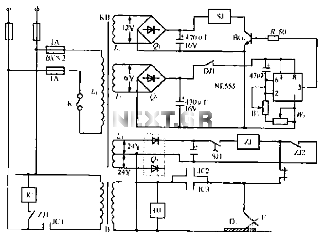
The NE555 timer circuit functions as a vibration generator. The input pin 3 produces pulse frequencies ranging from 5 to 20 Hz. The circuit includes a fan that operates within a bamboo enclosure. The barrel section is designed to...
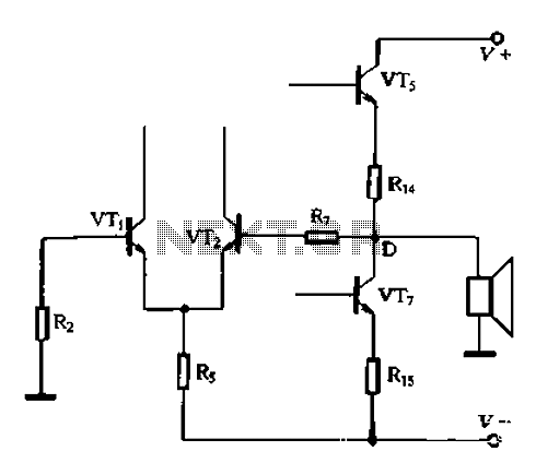
A, B, and C represent indirect person capacitance. The new access capacitor C is known as the bootstrap capacitor. The self-bootstrap capacitor can increase the voltage at point A. When static, Vi = 0V, the midpoint voltage VD is...
Warning: include(partials/cookie-banner.php): Failed to open stream: Permission denied in /var/www/html/nextgr/view-circuit.php on line 713
Warning: include(): Failed opening 'partials/cookie-banner.php' for inclusion (include_path='.:/usr/share/php') in /var/www/html/nextgr/view-circuit.php on line 713