
Synchronous System
The circuit is designed to provide precise measurements of low resistances while minimizing the impact on the system under test. The use of a synchronous detection scheme is critical in this application, as it enables the circuit to reject common-mode noise and interference, which are prevalent in low-level measurements.
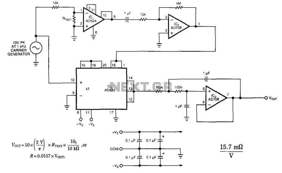
The 10-V peak, 1-kHz carrier signal generated serves as a reference for the synchronous detection process. By injecting a controlled 1-mA reference current into the unknown resistor, the circuit ensures that the voltage drop across the resistor can be accurately measured without introducing significant error or disturbance.
The amplification stage, consisting of instrument amplifier IC1 and precision op amp IC2A, is crucial for enhancing the small voltage signal generated across the resistor. With a gain of 100,000, this stage significantly boosts the signal, making it suitable for further processing. The choice of operational amplifiers is essential, as they must possess low noise characteristics and high input impedance to avoid loading the circuit under test.
The synchronous detector IC3 plays a vital role in demodulating the amplified voltage signal. This component extracts the desired DC component from the AC signal, effectively isolating the information related to the resistance measurement. Following this, operational amplifier IC2B acts as a low-pass filter, which is designed to suppress high-frequency noise and other unwanted signal components. By allowing only the DC voltage, which is directly proportional to the resistance, to pass through, the filtering stage enhances the accuracy and reliability of the measurement.
Overall, this circuit design exemplifies a sophisticated approach to low-resistance measurement, combining advanced signal processing techniques with careful component selection to achieve high precision while minimizing the influence of external factors. The circuit uses a synchronous-detection scheme to measure low-level resistances. Other low-resis-tance-measuring circui ts sometimes inject unacceptable large currents into the system-under-test. This circuit synchronously demodulates the voltage drop across the system-under-test and can hence use* extremely low currents while measuring resistance. The 10-V (pk), 1-kHz carrier generator injects a 1-mA reference current into unknown resistor, iTEST.
Instrument amplifier IC1 and precision op amp IC2A amplify the voltage across iTEST by a gain of 100 000. Synchronous detector IC3 demodulates this voltage, then op amp IC2B acts a low-pass filter on the demodulated voltage.
The low-pass filtering will attenuate all uncorrected disturbances (such as noise, drift, or offsets), while passing a dc voltage that is proportional to the unknown resistance. 🔗 External reference
Related Circuits
The TTY and the detector-transmitter unit are connected to separate phone jacks on the same line. When the ring sensor detects an incoming phone call, it activates the transmitter, which sends an RF signal to the receiver in the...
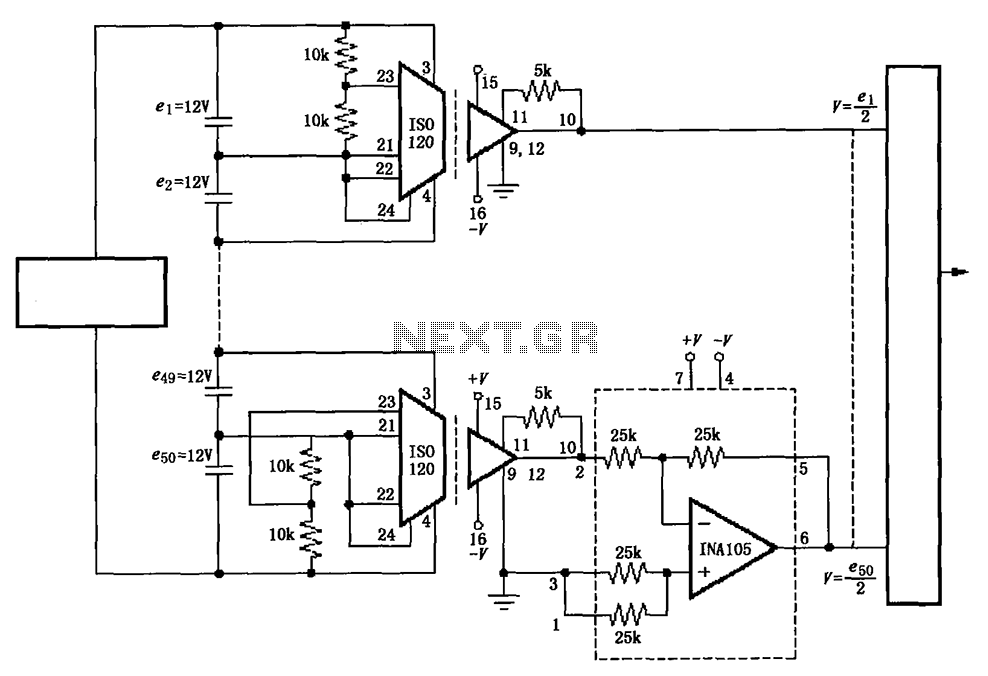
The circuit utilizes the ISO120 and INA105 instrumentation amplifiers to create a battery monitoring system for a 600V battery setup composed of 50 series-connected 12V batteries. This circuit is designed to detect charging and discharging conditions to prevent overcharging...
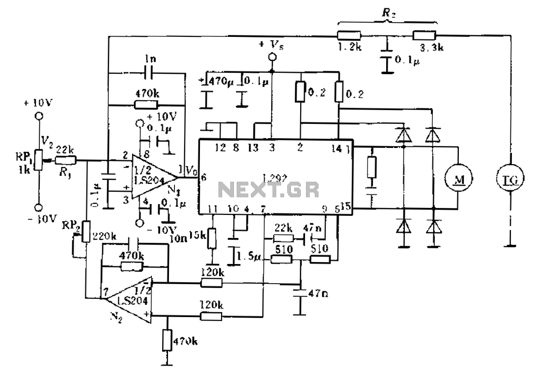
An alternative solution involves enhancing the existing feedback signal directed to an error amplifier summing junction, which is integrated into a current feedback loop for improvement. The L292 circuit demonstrates that the electrical current is proportional to the average...

This figure illustrates a block diagram of modern automated systems that incorporate closed-loop feedback for motion control. These systems typically feature a servo system consisting of feedback elements and a motor driver, which work together to provide accurate and...
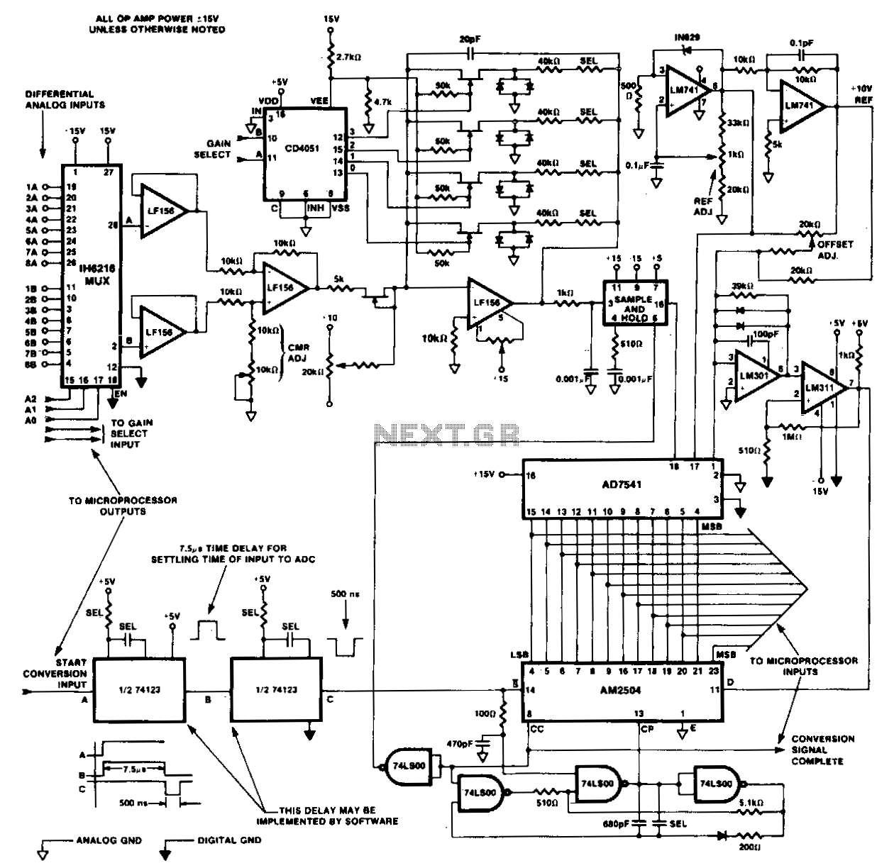
The front end of the DAC is configured differentially using dual eight-input IC multiplexer 1H6216 and three LM156 operational amplifiers. Following the differential amplifier is the programmable gain stage, which includes a low-pass filter on the output that feeds...
The circuit presented is a simple yet effective alarm system designed to protect an object. It requires no specialized devices and can be constructed using commonly available components. The primary alarm-triggering element is a reed switch. Any optical or...