
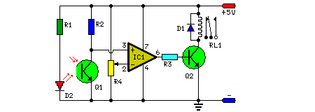
RC (Remote Control) Switch
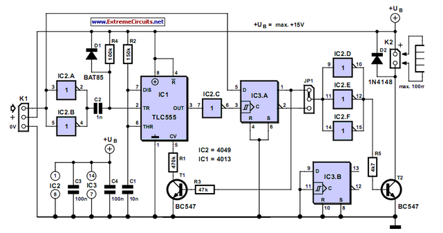
In the context of remote control models, incorporating switching functionality can significantly enhance user experience and operational capabilities. The implementation of this feature typically involves using a combination of resistors (R) and capacitors (C) to create an RC circuit. This circuit can be utilized to control various electronic components, such as LEDs for lighting effects, motors for movement, or other accessories that require activation or deactivation based on user input.
To design an effective switching circuit for an RC model, one can employ a simple transistor switch. The transistor acts as a gate that can be controlled by a signal from the remote control unit. When the signal is received, the transistor allows current to flow through the load (e.g., an LED or motor), turning it on. The choice of transistor (NPN or PNP) will depend on the specific requirements of the circuit, including the voltage and current ratings.
Additionally, incorporating a resistor in series with the load can help limit the current, protecting the components from damage. A capacitor may also be included in the circuit to smooth out fluctuations in the power supply, ensuring stable operation of the connected devices.
For more complex applications, microcontrollers can be integrated into the design to provide programmable control over the switching functions. This allows for advanced features such as dimming lights, controlling the duration of activation, or even creating patterns of light sequences.
Overall, the addition of switching functionality in an RC model not only enhances its interactivity but also expands its operational capabilities, making it a more versatile and engaging device.It is sometimes necessary for an RC (remote control) model to contain some kind of switching functionality. Some things that come to mind are lights on a.. 🔗 External reference
Related Circuits
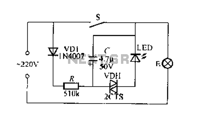
Figure 2 illustrates a circuit for a flashing light switch indicator. When switch S is closed, the normal light E illuminates, while the flashing light indicates a power loss when the system is not operational. When switch S is...

The installation of security cameras in offices, homes, or shops has become economically viable due to the decreasing prices of security cameras. However, it is not efficient if we... The integration of security cameras into various environments such as offices,...
When VOUT is very low during startup or in the event of a short-circuit fault at the output, the switching regulator must operate at low duty cycles to keep the power switch current within the current limit range. This...
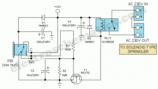
The motion sensor switch circuit is a motion sensor-controlled automatic water sprinkler, but an alarm or light function can be easily added as well. The motion sensor switch circuit utilizes a passive infrared (PIR) sensor to detect motion within...
Home appliances are typically controlled using switches, sensors, and similar devices. However, physical interaction with switches can pose risks, particularly in the event of short circuits. The circuit presented here eliminates the need for physical contact to operate the...
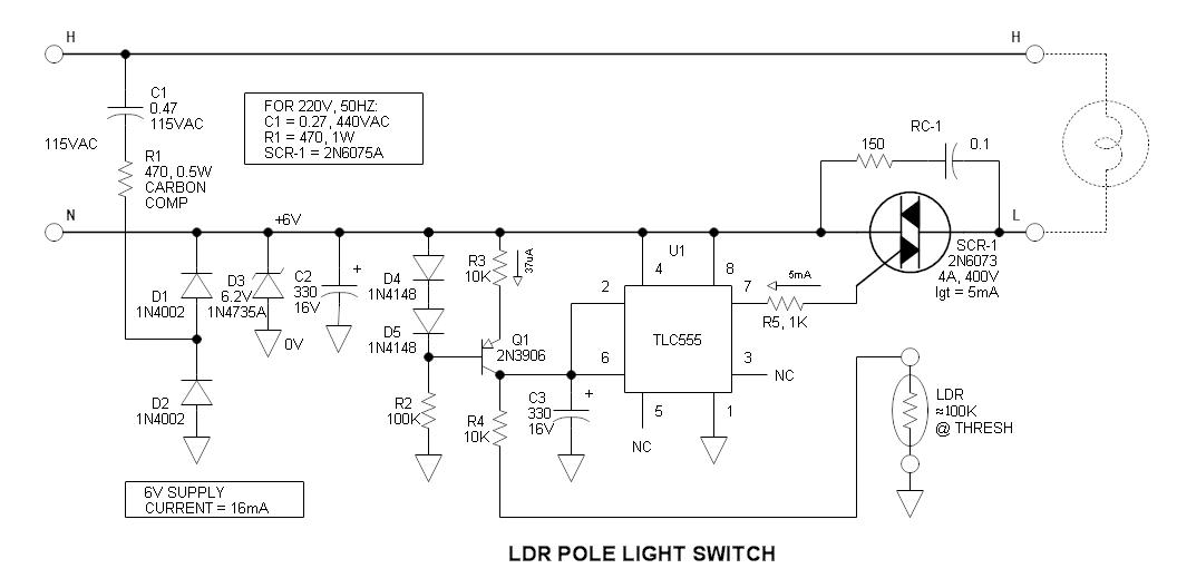
The vintage pole light, which is 62 years old, has traditionally been controlled by a timer, leading to ongoing frustration due to the need for adjustments with changing seasons. After accidentally knocking it over, an update was deemed necessary....
Warning: include(partials/cookie-banner.php): Failed to open stream: Permission denied in /var/www/html/nextgr/view-circuit.php on line 713
Warning: include(): Failed opening 'partials/cookie-banner.php' for inclusion (include_path='.:/usr/share/php') in /var/www/html/nextgr/view-circuit.php on line 713