
Isolated 24V Relay Controller
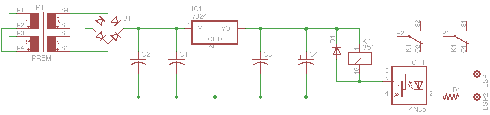
In this project, a supply of 24V relays was utilized, along with several trays of board-mount transformers featuring dual primaries (for 120/240 VAC operation) and dual secondaries that could be configured for 24 VAC output. A selection of 24V coil relays, capable of handling 5 Amps at 125 VAC and equipped with sockets for board or panel mounting, were also available. A point-to-point controller was employed in the relay-controlled receptacle project, which functioned effectively and could be operated by 3.3V, 5V, or 12V control circuits without requiring modifications. The controller included a protection resistor and depended on an external current-limiting resistor. Driving the optoisolator's source was straightforward, akin to driving an LED. The onboard transformer produced a sufficiently high rectified output, necessitating a regulator, yet it allowed for a compact combined supply and control board that could be integrated into existing line-operated devices.
Interest from peers in control boards led to the decision to design a proper printed circuit board (PCB) and have several units manufactured, which would reduce the size of the device and assembly time. The board layout was completed during personal project time and sent for fabrication. This marked the first board produced through the service that evolved from the DorkbotPDX prototype PCB service, OSH Park, which maintained competitive pricing and quality. After 12 days, nine boards measuring 2.15" x 1.35" were received, each costing approximately $4.95 USD. To optimize size and cost, some components were positioned on the underside of the board beneath the power transformer. The bridge rectifier, 24V regulator, and a decoupling capacitor were placed underneath, requiring them to be soldered first to allow for lead trimming before adding the transformer. Once the components on the bottom were soldered and their leads trimmed as closely as possible to the board, the remaining components could be installed on the top side. A discrepancy in lead spacing for the main filter capacitor meant it was installed with leads sticking up from the board, but this did not significantly affect the overall design as it remained shorter than the power transformer. The board was designed for installation within devices to be controlled by an external circuit, featuring four large vias in the corners for versatile mounting options.This is a common control voltage in industrial and telecommunications equipment, so the relays are common in surplus equipment. Many will actuate equally well on AC or DC, which makes them an easy solution when the control voltage is switched mechancially, as in the case of limit switches or magnetic reed switch sensors.
Unfortunately, they`re not so simple to interface directly to microcontrollers as they require a separate supply and level shifting circuitry. Even so, one can easily control them with a separate supply and optoisolator. An optoisolator uses the illumination of a (mostly infared) LED to trigger a photosenitive resistor or transistor. This provides galvanic isolation between the control circuit and the device being switched, which also means that the power supplies don`t have to be the same voltage, or even share a common ground.
Additionally, transistor-type optoisolators in DIP packages are extremely common and cheaply available if you don`t have a few in the parts bin. They also provide an easy method to control devices using a current loop. Using a current loop and a control current rather than a control voltage makes interfacing with a wide range of control voltages easy.
I came across a few things that made this project possible and/or necessary. First, I had a large supply of 24V relays sitting around. Second, I had a few trays of Prem board-mount transformers with dual primaries (120/240 VAC operation) and dual secondaries that could be series-wired for 24 VAC output. Finally, I came across a bunch of 24V coil relays that could handle 5 Amps @ 125 VAC and came with sockets that could be board or panel mounted.
I used one of them and a point-to-point controller in this relay-controlled receptacle project: The controller worked fine and could be driven by 3. 3/5/12 Volt control circuits without modification, since the controller included only a protection resistor and relied on an external current-limiting resistor.
Driving the optoisolator`s source is literally as simple as driving an LED. The onboard Prem transformer has high enough rectified output to require a regulator, but still made for a fairly compact combined supply and control board. Small enough to be integrated into existing line-operated devices. A few friends were interested in control boards, so I decided to lay out a proper PCB and have a few produced.
This would make the device a bit smaller and reduce assembly time. I laid out the board during my personal project time at work and sent it off to be fabricated. This was the first board to go off to the service that evolved from the DorkbotPDX prototype PC board service, OSH Park. The price is the same, and the quality is every bit as good. 12 days later, I had nine 2. 15" x 1. 35" boards that cost around $4. 95 USD each: In an effort to make the boards smaller (and cheaper!), some components were placed on the bottom of the board under the power transformer.
The bridge rectifier, 24V regulator, and a decoupling capacitor were placed under the transformer. These had to be soldered first, since their leads would have to be trimmed before the transformer was added: After the components on the bottom were soldered and their leads trimmed as close to the board as possible, the topside components could be added. The main filter capacitor in the supply ended up being 0. 2" lead spacing when it should`ve been 0. 3" spacing, so it was installed sticking up from the board. That shouldn`t make too much difference as it`s still shorter than the power transformer. Here`s the board with the remainder of components installed (sans protection diode, forgot to bring some!): The board was designed to be installed inside devices to be controlled by an external circuit.
In order to provide the most versatile mounting options, I placed four large vias in the corners of the boards. These ca 🔗 External reference
Related Circuits
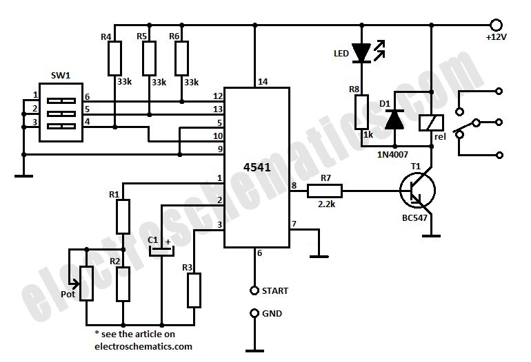
To initiate the timing process, there are two options available: either connect the START point to ground (GND), in which case the timer activates when connected to the voltage supply, or employ a switch to start the timer. The timing...
This is a circuit for alternative sources selection. It combines mechanical selection using a rotating switch S1, the electronic drive of the relays RL 1-10 and also the optical indication of the selection by the Display DSP1. The function...
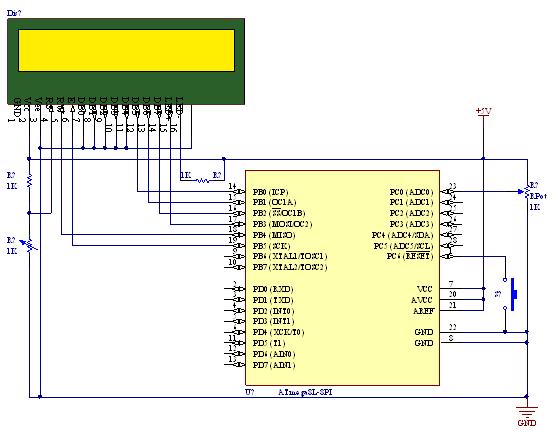
A straightforward tutorial on utilizing the ADC (Analog to Digital Converter) unit of the AVR microcontroller, demonstrated with the Atmega8, including a circuit diagram and code examples. The ADC unit in the Atmega8 microcontroller is a crucial component that allows...
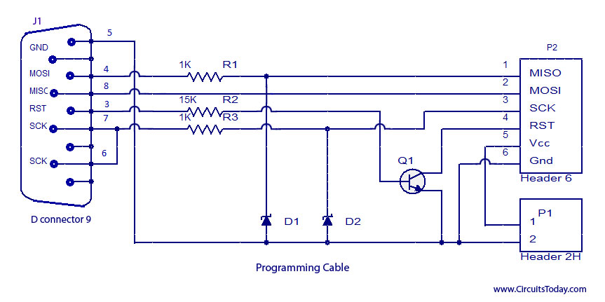
ISP programmer with circuit diagram for AVR Atmega32 microcontroller. This ISP burner circuit is an adaptation of the Pony programmer and uses PonyProg software. The ISP (In-System Programming) programmer designed for the AVR Atmega32 microcontroller allows for programming the microcontroller...
The temperature of a quartz crystal oscillator must be maintained at a constant level to ensure stable frequency operation. This oven temperature controller is appropriate for this purpose. The operation of quartz crystal oscillators relies heavily on temperature stability, as...
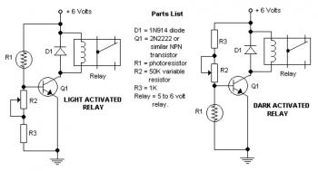
The potentiometer adjusts the trigger level. The diode in the circuit diagram is specified as 1N914, which is suitable for light-duty relays; however, since the 1N914 is a signal diode, it is not ideal for this application. A 1N4001...