
Adjustable Symmetrical Power Supply Using LM317 and LM337
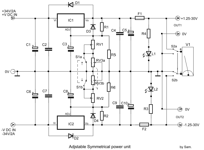
The adjustable power supply circuit is typically composed of several key components to ensure stable operation and precise voltage control. The core of the circuit often includes a voltage regulator IC, which is capable of handling the specified voltage range. Common choices for such applications are adjustable linear regulators like the LM317 or switching regulators for higher efficiency.
The circuit layout should incorporate input and output capacitors to filter voltage spikes and ensure stability. The input capacitor, often a tantalum or electrolytic type, is placed close to the input pin of the voltage regulator to minimize inductance and improve transient response. Similarly, an output capacitor is used to stabilize the output voltage and reduce ripple, particularly under varying load conditions.
An adjustable resistor, or potentiometer, is employed to set the desired output voltage. This resistor is connected to the feedback pin of the voltage regulator, allowing for fine-tuning of the output voltage within the specified range. To enhance the circuit's performance, it is crucial to select a potentiometer with a suitable resistance value that complements the regulator's feedback requirements.
The circuit should also include protection features such as thermal shutdown and current limiting to prevent damage during overload conditions. A heatsink may be necessary for the voltage regulator, especially when operating at higher currents or voltage differentials, to dissipate heat effectively.
Furthermore, the design may incorporate LED indicators to provide visual feedback on the output status, as well as fuses or circuit breakers for added safety. The entire assembly should be housed in a well-ventilated enclosure to facilitate heat dissipation and protect against environmental factors.
Overall, this adjustable power supply circuit serves a wide range of applications, from laboratory testing to powering various electronic devices, ensuring reliability and versatility in operation.The circuit was designed to provide an adjustment with a power supply that is symmetrically designed while providing a voltage range of 1.25V to 30V at 1A.. 🔗 External reference
Related Circuits

Miniature isolated AC/DC power supply. This circuit employs a novel method to generate a fully isolated and regulated 5 volts at 30 mA from the 120 VAC power line. It utilizes two tiny SCRs that operate alternately. The miniature isolated...

To create the circuit, connect a switch as an input and an LED as an output to the Arduino. The components required include a switch, an LED, a 10kΩ resistor, a 470Ω resistor, a blue or yellow jumper wire,...

The resistors may be rated at 1/8 watt. The zener diode can be either a 250 mW or a 1W component (the part number will differ). The electrolytic capacitor is a standard type, and its value can vary (larger...

A typical computer motherboard CPU power supply circuit is primarily composed of the main power supply management chip RT9241 and additional components from the power management chip RT9600. The voltage command signal from the CPU is input into the...
This oscillator is known as the Colpitts oscillator and is voltage-controlled to facilitate frequency modulation (FM) and phase-locked loop (PLL) control. The transistor T1 should be a high-frequency (HF) transistor for optimal performance; however, in this instance, a common...
The Inter-Power SWR-5 upper right isn't worth a penny. Got it from a mate to use with a beacon, but I burnt it out with only 3.5-4W morse signal on 70cm. Removed the bridge and installed my own pick-up...