
Telephone call meter using calculator & COB
The circuit design incorporates a COB sourced from an analogue quartz clock, which serves as the primary timing mechanism for generating the required clock pulses. The integration of the COB with the calculator is achieved through a straightforward connection scheme involving a transistor that interfaces with the calculator's input. The use of a bridge rectifier formed by diodes ensures that the clock pulses are appropriately conditioned to produce a stable 1Hz signal, which is crucial for accurate timing and counting of call pulses.
The circuit's power supply is derived from a low-voltage battery, which not only enhances portability but also contributes to the low power consumption profile, allowing for prolonged battery life. The choice of components, including the diodes and the transistor, is critical to maintaining the integrity of the signal and ensuring reliable operation over extended periods.
In summary, this circuit presents an efficient solution for monitoring telephone call durations and costs by leveraging readily available components and simple circuitry. Its ability to adapt to various pulse rate formats and its user-friendly interface make it a valuable tool for users requiring precise call metering.A simple calculator, in conjunction with a COB (chip-on-board) from an analogue quartz clock, is used to make a telephone call meter. The calculator enables conversion of STD/ISD calls to local call equivalents and always displays current local call-meter reading.
The circuit is simple and presents an elegant look, with feather-touch operation. It consumes very low current and is fully battery operated. The batteries used last more than a year. Another advantage of using this circuit is that it is compatible with any type of pulse rate format, i. e. pulse rate in whole number, or whole number with decimal value. Recently, the telephone department announced changes in pulse rate format, which included pulse rate in whole number plus decimal value.
In such a case, this circuit proves very handy. To convert STD/ISD calls to local calls, this circuit needs accurate 1Hz clock pulses, generated by clock COB. This COB is found inside analogue quartz wall clocks or time-piece mechanisms. It consists of IC, chip capacitors, and crystal that one can retrieve from scrap quartz clock mechanisms.
These can be purchased from watch-repairing shops for less than Rs 20. Normally, the COB inside clock mechanism will be in good condition. However, before using the COB, please check its serviceability by applying 1. 5V DC across terminals C and D, as shown in the figure. Then check DC voltage across terminals A and B; these terminals in a clock are connected to a coil. If the COB is in good condition, the multimeter needle would deflect forward and backward once every second. In fact, 0. 5Hz clock is available at terminals A and B, with a phase difference of 90o. The advantage of using this COB is that it works on a 1. 5V DC source. The clock pulses available from terminal A and B are combined using a bridge, comprising diodes D1 to D4, to obtain 1Hz clock pulses.
These clock pulses are applied to the base of transistor T1. The collector and emitter of transistor T1 are connected across calculator`s =` terminals. The number of pulses forming an equivalent call may be determined from the latest telephone directory. However, the pulse rate (PR) found in the directory cannot be used directly in this circuit. For compatibility with this circuit, the pulse rate applicable for a particular place/distance, based on time of the day/holidays, is converted to pulse rate equivalent (PRE) using the formula PRE = 1/PR.
You may prepare a look-up table for various pulse rates and their equivalents (see Table). Suppose you are going to make an STD call in pulse rate 4. Note down from the table the pulse rate equivalent for pulse rate 4, which is 0. 25. Please note that on maturity of a call in the telephone exchange, the exchange call meter immediately advances to one call and it will be further incremented according to pulse rate. So one call should always be included before counting the calls. For making call in pulse rate 4, slide switch S1 to off` (pulse set position) and press calculator buttons in the following order: 1, +`, 0.
25, =`. Here, 1 is initial count, and 0. 25 is PRE. Now calculator displays 1. 025. This call meter is now ready to count. Now make the call, and as soon as the call matures, immediately slide switch S1 to on` (start/standby position). The COB starts generating clock pulses of 1 Hz. Transistor T1 conducts once every second, and thus =` button in calculator is activated electronically once every second.
The calculator display After finishing the call, immediately slide switch S1 to off` position (pulse set position) and note down the local call meter reading from the calculator display. If decimal value is more than or equal to 0. 9, add another call to the whole number value. If decimal value is less than 0. 9, neglect decimal value and note down only whole numbers. To store this local call meter reading into calculator memory, press M+` button. Now loc 🔗 External reference
Related Circuits
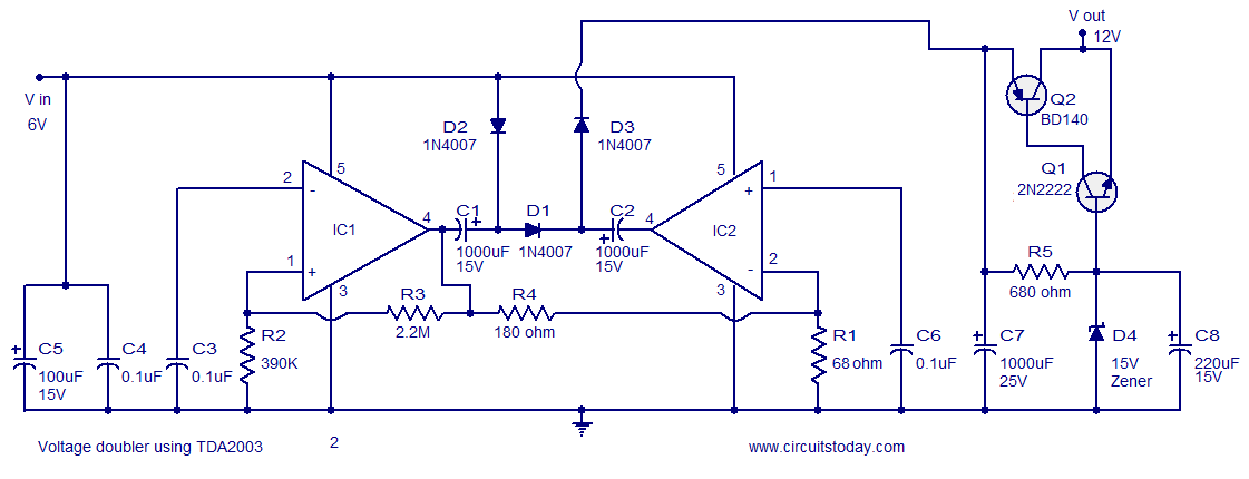
A reliable voltage converter circuit that operates between 6 to 12 volts, utilizing the audio amplifier IC TDA 2003. This voltage doubler circuit can be assembled on a Vero board. The voltage converter circuit designed with the TDA 2003 audio...
Pulses are received by the timer from the distributor points. When the timer output is high, Meter M receives a calibrated current through R6. The meter does not... The circuit described involves a timer that receives pulse signals from distributor...
While it may lack the aesthetic appeal of traditional mercury barometers featuring elongated glass tubes mounted on intricately carved wood, the Torricelli barometer presented here serves as a functional equivalent and an electronic representation of the original Torricelli barometer....
The given circuit, when connected in parallel to a telephone, displays the number dialled from the telephone set using the DTMF mode. This circuit can also show the number dialled from the phone of the called party. This is...
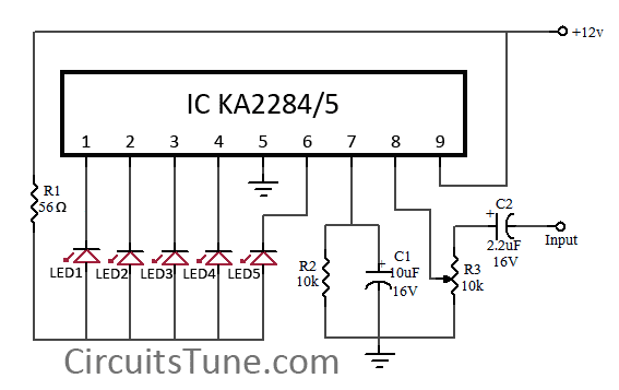
This is a simple circuit diagram of a 5-LED audio VU meter utilizing the ICs KA2284 or KA2285. The KA2284 and KA2285 are monolithic integrated circuits designed as logarithmic display driver ICs. They serve as bar-type display drivers for...
The Model LM-13 Crystal Calibrated Frequency Indicating Equipment has been specifically designed to provide a simple, accurate, and reliable frequency indication for the crystal calibrated type, intended for use in the U.S. Naval radio service. It is adaptable for...