
BA3884 application circuit within the circuit and a
To eliminate delay caused by phase distortion, the circuit employs a fixed high-frequency constant for the high-frequency audio segments, which are subject to a lag of 80 microseconds. Conversely, the bass frequencies experience a lag of 3600 microseconds. This phase compensation ensures that the audio delays are corrected, effectively mitigating phase distortion.
For amplitude compensation, the circuit addresses the inadequacies of speaker harmonic amplitude response. This is achieved using a peak detector filter and a voltage-controlled amplifier (VCA) that automatically adjusts harmonic amplitude as needed. The correction is facilitated by two DC voltages controlled by an external voltage divider circuit, with one voltage applied to the CTL O end. The second DC voltage is derived from the peak detector and processed through the HPF to provide the VCA with the necessary input signal for compensation.
After amplitude correction, the characteristics of harmonic sounds are restored and enhanced, resulting in a playback system that delivers high-resolution, high-definition sound with natural timbre. The adjustment of the DC voltage at the CTL1 end (pin 8) is performed by dividing the base voltage. When activated, this state switches the BBE function on, leading to a change in voltage from 4.5V to 0V, enhancing the clarity of the processed audio signal by 9.5 dB.
The system also incorporates a bass boost circuit to achieve an optimal balance in sound reproduction. This circuit operates within the frequency range of 50 Hz to 150 Hz, utilizing a voltage divider circuit (R1) to adjust the DC voltage at the RL2 terminal (pin 7). When the voltage changes from 4.5V to 0V, the bass boost enhances the audio by 8.7 dB. This bass boost is critical for achieving a balanced sound reproduction across the entire audio spectrum.
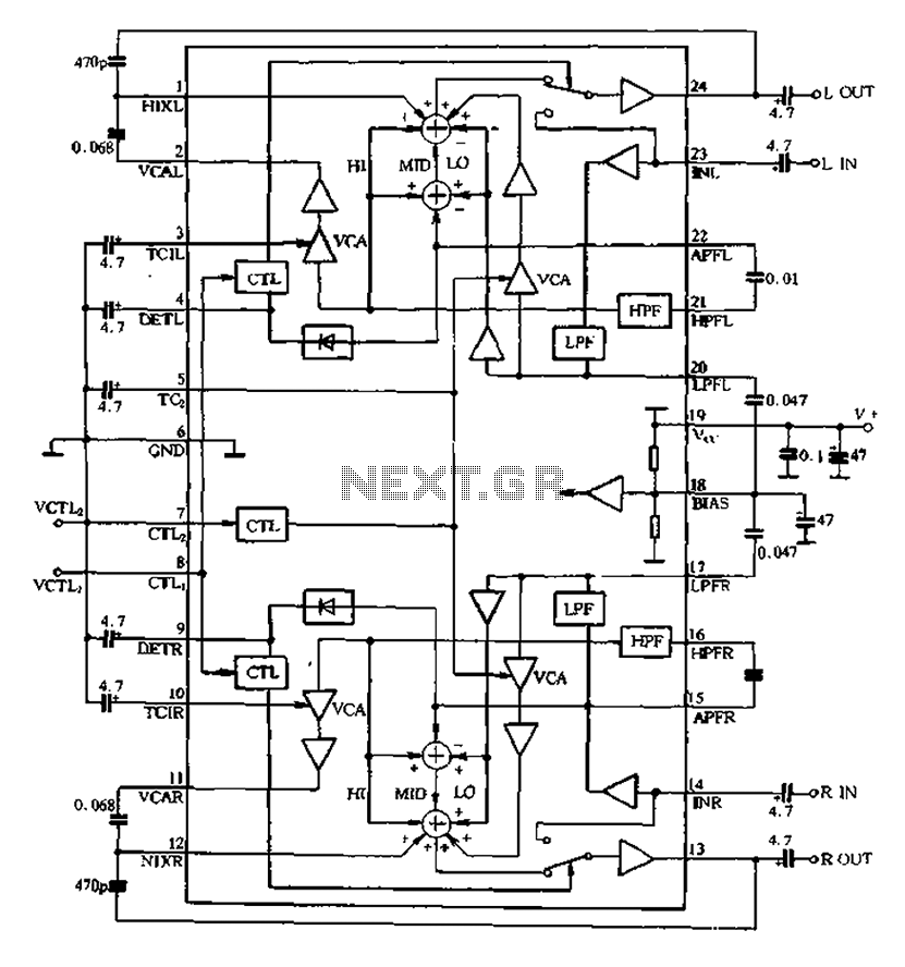
The BA3884 circuit is designed to provide comprehensive audio processing capabilities, ensuring high fidelity in sound reproduction while addressing phase and amplitude discrepancies inherent in audio signals. BA3884 DC operating voltage of 5.4 ~ 12,3V, its internal circuit principle and application circuit as shown in Figure 5-16. The circuit is a two-channel processing circuit, the processing circuit includes two identical sets t be completed, following which the audio signal. Phase compensation. 14.23 audio signal input pins are two channels lc and by the low-pass filter LPF, a band-pass filter BPF, high-pass filter HPF divider 20 a -150Hz, 150Hz ~ 2.4kHz and 2.4kHz ~ 20kHz three months bands and processed separately, and finally the processed signal output by the pin 13, 24 are added after the synthesis, respectively. Since the sound of the fundamental tone frequency band located higher harmonics in the high frequency band, high in order to eliminate the delay caused by the phase distortion of the electric circuit uses a fixed high frequency constant, so that the high range audio segment with respect to a lagging 80.
Bass treble frequency band relative lag 3600. Because of the bass frequencies were lagging process, so that the relatively high so just get the audio delays to compensation and correction, phase distortion is eliminated. Amplitude compensation (harmonic compensation) o In order to compensate for speaker harmonic amplitude response is inadequate, from a high peak detector filter and a voltage controlled amplifier VCA harmonic amplitude of automatic control as needed.
Correction, compensation for directors from two DC voltage to control a DC voltage is provided by an external voltage divider circuit, added CTL O end; another DC voltage by the peak detector after detection of the input signal obtained through the HPF frequency harmonic wave to VCA input circuit is completed by a special compensation correction. After amplitude correction, reflecting the characteristics of harmonic sounds fine restored and strengthened so that the playback systemm a high resolution, high-definition sound and natural timbre oCTL1 end of the DC voltage circuit 2 is adjusted by dividing the base), when the opening when the state is working BBE off K to ON bamboo bit .CTL1 end 8-pin voltage changes from the 4.5V-Oy, the resolution © Ju processed audio signal clarity by the OdB9,5dBo boost bass contour.
restored the higher harmonics of the phase and amplitude, the need to achieve the best bass proper balance of the treatment system uses a bass boost circuit outline and achieve optimal linear promoted from within the range of 50 N150Hz the lifting by the lifting circuit a voltage divider circuit RPi be adjusted when the DC voltage rL2 terminal 7 feet by 4,5V bucket OV changes, bass lift the OdB + 8.7dB improvement. bass boost through the whole high bass sound reproduction system to achieve a balanced sound reproduction.
Related Circuits
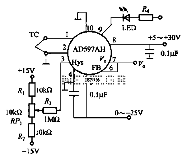
An automatic electric furnace temperature controller is illustrated. The closed circuit consists of a temperature detection output control loop; as the temperature increases, the output voltage rises until it reaches a preset temperature value, at which point the output...
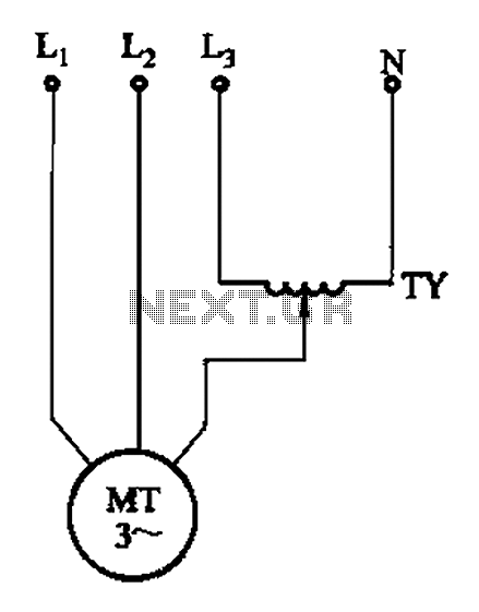
The circuit illustrated in Figure 3-175 features a regulator connected between one phase and neutral. It is designed for use with a 380V torque motor. This method offers advantages over the serious line imbalance approach, resulting in improved operating...
Leo Esaki invented the tunnel diode in 1957 while working at Sony (then known as Tokyo Tsushin Kogyo). Tunnel diodes feature a very narrow, heavily doped p-n junction approximately 10 nm wide, which exhibits a broken bandgap. This configuration...
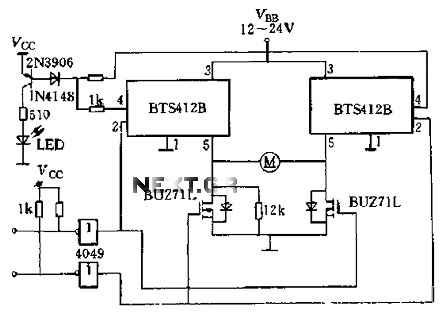
The BTS412B functions as two high-side power MOSFET switches, while two BU271L (50V, Zhang 1n) serve as low-side switches, forming a bi-directional H-bridge DC motor drive circuit. This configuration is designed for electrical automatic door systems, capable of handling...
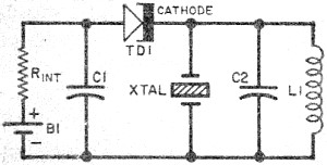
This circuit is a conventional Pierce-type oscillator that utilizes a JFET. It operates with fundamental mode crystals, offering decent performance and reliability when a low noise JFET is employed. The feedback is regulated by the capacitance of C1 from...
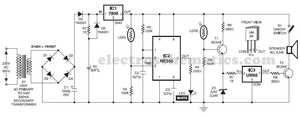
This musical light alarm circuit is very simple and uses only seven components, including a light-dependent resistor (LDR) and a 3.6V battery or three 1.2V rechargeable batteries. The well-known UM66 is utilized as the sound generator, providing a pleasant...