
Automatic Rain Sensing Wiper System using 555 Timer
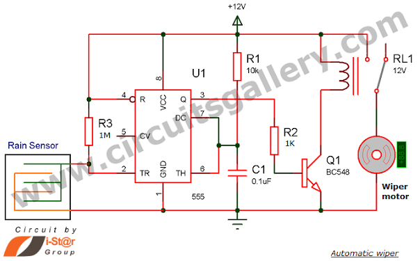
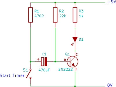
The rain-sensing wiper system utilizes a 555 timer IC in monostable configuration to create a reliable and efficient mechanism for automatic wiper activation. The two metal sheets act as capacitive sensors that detect the presence of water droplets on the windscreen. When raindrops bridge the gap between these sheets, they generate a change in capacitance that triggers a negative voltage at the timer's trigger pin.
In monostable mode, the 555 timer remains in a stable low state until it receives a trigger signal. Once triggered, the output goes high for a predetermined duration, which can be adjusted by varying the connected resistor and capacitor values. This output is then used to energize a relay through a transistor switch. The transistor, typically an NPN type, is used to amplify the current from the output of the 555 timer to activate the relay coil.
The relay serves as an electromechanical switch that controls the wiper motor. When the relay is energized, it closes its contacts, allowing current to flow to the wiper motor, which starts the wiper operation. The duration of wiper operation can be customized by adjusting the timing components of the 555 timer circuit. This design ensures that the wipers operate only when rain is detected, thereby conserving energy and enhancing driver visibility during adverse weather conditions.
In summary, the rain-sensing wiper circuit effectively combines the 555 timer IC, capacitive sensing technology, and relay control to create a responsive and automated wiper system that enhances vehicle safety and convenience.Have you seen Audi, Lexus or Ford rain sensing wipers and wondered how they work in these vehicles They are handled by sensors at the center of the windscreen which detects rain water and turns on the wiper motor. Here is the working of rain sensitive wipers with circuit schematic. The main component of this circuit is a 555 timer IC that works i n monostable mode. Two metal sheets fixed at a small distance apart are used as rain detector sensors. From the working of a monostable 555 timer, a negative voltage on the trigger pin will cause a high output. So when it rains, trigger pin gets a negative voltage. Output of one shot 555 (monostable) is connected to a relay through a transistor. The transistor acts as a switch for the relay to turn ON the wiper motor during rain. 🔗 External reference
Related Circuits
The documents, software, tools, and links are provided to enhance the capabilities of electronics students, hobbyists, or professionals by sharing information. This information and the associated links should be utilized by website visitors at their own risk and responsibility....
This circuit uses a sensor made of a small piece of etched PC board and a simple SCR circuit to detect rain and sound a buzzer. The SCR could also be used to activate a relay, turn on a...
This circuit utilizes two CMOS ICs: a 4011 quad 2-input NAND gate and a 4020 14-stage ripple binary counter. Upon powering on, resistors R2 and capacitor C2 generate a brief reset pulse, ensuring that the output pin Q1 of...
A single transistor timer circuit tutorial designed for beginners in electronics. This is an easy electronic circuit that can be constructed on a breadboard. The single transistor timer circuit utilizes a transistor as the primary switching element to create a...
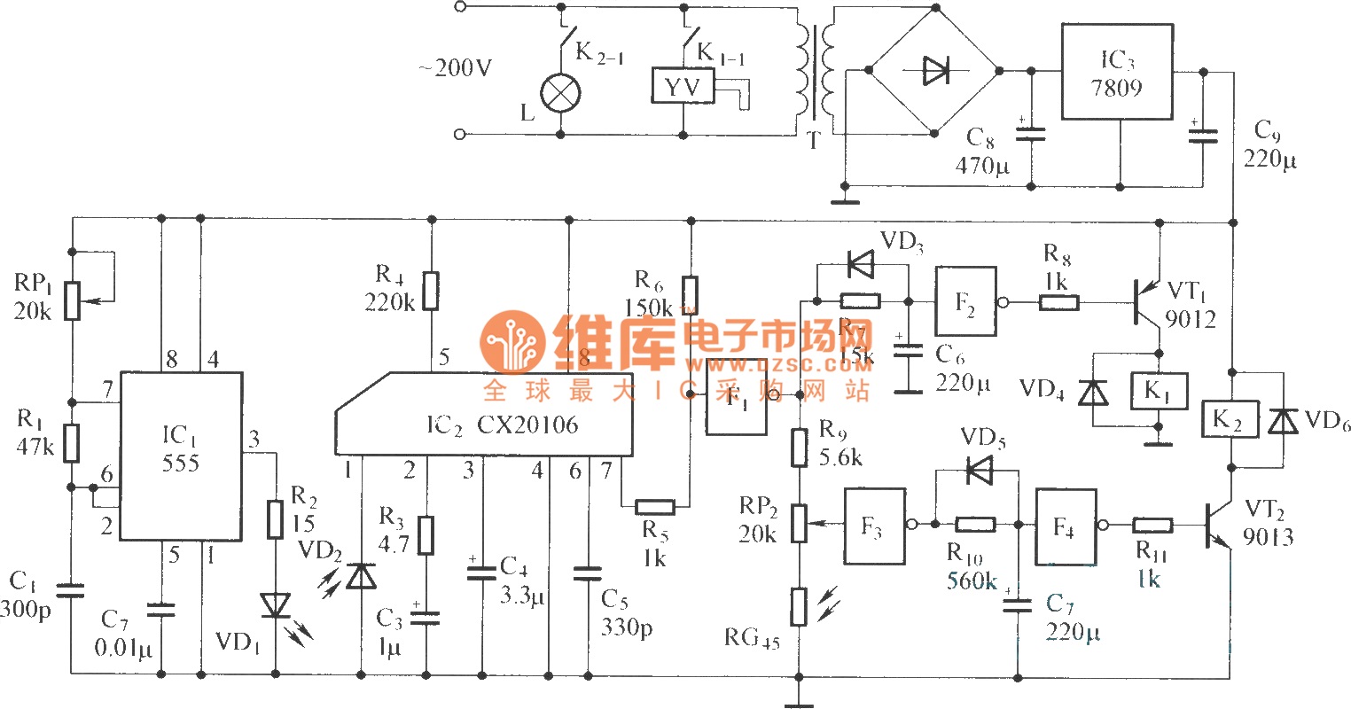
The circuit consists of the following components: (1) An infrared emitter which utilizes a multi-harmonic oscillator based on a 555 timer circuit. The oscillation frequency is determined by the values of RP1, R1, and C1, resulting in a frequency...
When configured as an input, there is a subtle issue. If the input has its pull-up enabled, it may interfere with the circuitry that expects to see an analog-to-digital (A/D) input. Conversely, if the pull-up is not enabled, the...