
NTSC Video Using the 68HC908QY4
The circuit design described involves an input configuration that can either enable or disable pull-up resistors, impacting the expected signal levels at the A/D input. In the case of enabled pull-ups, the input may interfere with analog readings, while disabling them may leave the input floating or subject to undefined digital levels. This configuration is critical in applications where accurate analog-to-digital conversion is necessary, particularly in devices such as televisions that utilize Closed Captioning.
The Closed Caption Decoder is a pivotal component in modern television sets, especially those compliant with regulatory standards established for screen sizes above 13 inches. The compliance with 47 CFR 15.119 and 47 CFR 73.682(a)(22) ensures that the television can properly decode and display captioning data. The transmission of this data over line 21 of the video signal is essential for providing viewers with necessary information, such as program ratings and captions.
The schematic must account for the IRE Units, which define the signal levels for proper synchronization and decoding. The critical levels of 0, 25, 40, and 50 IRE Units must be maintained to ensure that the Run-In Clock operates correctly and that the decoder can accurately interpret the incoming signals. The use of a square wave instead of a sine wave simplifies the design, as it provides a clear and distinct timing reference for the decoder.
Furthermore, the design must include provisions for generating the Closed Caption bit stream in software, which will require careful timing and synchronization with the horizontal line cycle to ensure that the bit clock remains stable and accurate. The choice of clock frequency is crucial, as demonstrated by the differing tolerance levels of various television models, highlighting the need for precise engineering in the design of this circuitry.When configured as an input there is a more subtle problem. If the input has its pullup enabled it could affect the circuitry that is expecting to see an A/D input. But if the pullupis not enabled, then when its A/D input is not selected it will be a digital input that is either left floating or it will be driven by a signal that could be somewhere between 0` and 1`.
Neither is a good idea. (I chose to not enable pull-ups. ) As I mentioned, since 1993 all TVs having a screen size of at least 13" manufactured for sale in the U. S. have been required to have a Closed Caption Decoder. TVs with smaller screens are not required to have the decoder (and I have not seen a small-screen TV that had one.
) The standards for Closed Captioning can be found in 47CFR15. 119 which can be downloaded by going to: and scrolling down to 15. 119 where you can download it in text or PDF formats. The technical standards for Closed Captioning are in 47CFR73. 682 (a) (22) which can be downloaded by going to and scrolling down to 73. 682 where you can download it in text or PDF formats. (22)(i) Line 21, in each field, may be used for the transmission of a program-related data signal which, when decoded, provides a visual depiction of information simultaneously being presented on the aural channel (captions). Line 21, field 2 may be used for transmission of a program-related data signal which, when decoded, identifies a rating level associated with the current program.
Such data signals shall conform to the format described in figure 17 of Sec. 73. 699 of this chapter, and may be transmitted during all periods of regular operation. On a space available basis, line 21 field 2 may also be used for text-mode data and extended data service information. The part that is relevant to us is where it mentions figure 17 of §73. 699. This section was mentioned earlier in this article because it contains a number of figures for NTSC standards.
There are some critical items in this figure that might not be obvious, such as, What is the Zero-Crossing of the Run-In Clock To show them more clearly I have redrawn part of the figure. IRE Units refers to the level of the signal. 0 IRE Units is the blanking level. 50 IRE Units is half of maximum brightness. (100 IRE Units would be maximum brightness. ) Notice that Sync is at 40 IRE Units. The Run-In Clock is specified to go between 0 and 50 IRE Units so that Zero Crossing refers to where the zero-value of the sine wave crosses the level of 25 IRE Units.
However, we won`t be making a sine wave. We`ll be using a square wave as shown in the next figure. If we were to use the bottom of the sine wave where it reaches 0 IRE Units as the zero-crossing we would be off by bit time and it wouldn`t work. (I know because that`s what I did the first time. ) You might think that with the low bit rate (503 KHz. ) and with such a robust reference clock a Closed Caption Decoder would be fairly tolerant of the exact frequency used.
I have a Philips Magnavox 25TRC1 that absolutely refuses to recognize a Closed Caption signal unless the clock is 32H. (Well, ok, the TV was manufactured in November 1994). A more modern Sharp 13N-M100B, manufactured August 2002, is much more tolerant (and the picture is excellent, too).
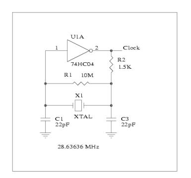
Since we are producing the Closed Caption bit stream entirely in software we are restricted to clock rates that can be produced by an integer number of bus cycles (BSET/BCLR instructions followed by a number of NOPS). My first effort used the NTSC sync generator previously described, operating at 28. 63636 MHz. to produce 455 bus cycles per Horizontal Line. Although I was able to produce a Closed Captioning bit clock very close to 503 KHz. , it was not at 32H because 455/32 is not an integer. Since i 🔗 External reference
Related Circuits
Each audio/video output can be switched to any of the eight inputs separately. One module drives one audio/video output and has a 34-pin connector to plug into the system interface. Video operational amplifiers (OPAs) can be used on the...
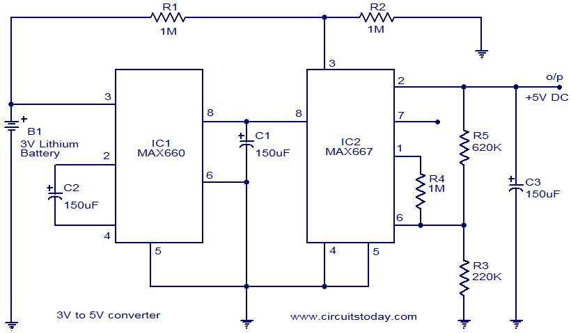
Voltage converter circuit diagram for converting 3 volts to 5 volts using CMOS monolithic ICs MAX660 and MAX667, which functions as a positive voltage regulator. The voltage converter circuit utilizes the MAX660 and MAX667 integrated circuits to step up a...
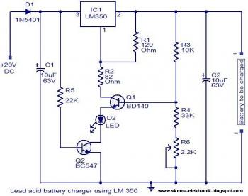
The circuit is designed as a constant voltage source with a negative temperature coefficient. The transistor Q1 (BD 140) serves as the temperature sensor, while transistor Q2 prevents battery discharge through resistor R1 when mains power is unavailable. The...

The LTC3113 fixed frequency buck-boost DC-DC converter can be utilized to design various power supply circuits that operate with input voltages that are above, below, or equal to the output voltage. The topology integrated into the IC ensures low...
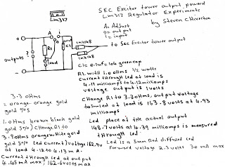
The following experiment demonstrates how Mr. Steven successfully extracted free energy from air using his home-built secondary exciter coil tower. He utilized this energy to power a small LM317 power supply unit. During the process, he hand-wound his coils...
The 2N3819 is an n-channel JFET specifically designed for RF and mixer applications, offering very low noise, minimal distortion, and excellent high-frequency gain. Creating a PCB can be accomplished in a few straightforward steps. Begin by using PCB design...