
transistor timer
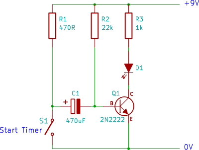
The single transistor timer circuit utilizes a transistor as the primary switching element to create a delay timer. This circuit can be particularly useful for applications such as turning on a light after a specified time or creating a simple delay in electronic projects.
The basic components required for this circuit include a NPN transistor (such as the 2N3904), resistors, a capacitor, and a power supply. The configuration typically involves connecting the transistor in a common emitter arrangement. The resistor connected to the base of the transistor controls the charging of the capacitor, which determines the timing interval.
In operation, when the circuit is powered, the capacitor begins to charge through the resistor. The time it takes for the capacitor to charge to a certain voltage level (typically around 0.7V for silicon transistors) will dictate how long the transistor remains in the ON state. Once the voltage across the capacitor reaches the threshold, the transistor will turn OFF, thereby stopping the flow of current through the load connected to the collector.
The timing can be adjusted by changing the values of the resistor and capacitor. A larger capacitor or resistor will result in a longer delay, while a smaller capacitor or resistor will decrease the timing interval. This circuit is an excellent introduction to understanding the behavior of capacitors and transistors in timing applications, providing foundational knowledge for more complex electronic designs.
Construction on a breadboard allows for easy modifications and experimentation, making it ideal for beginners to learn through hands-on experience. Proper attention should be given to the polarity of the components and the connections to ensure correct functionality.Single Transistor Timer Circuit tutorial for beginners in electronics. Easy beginner electronic circuit that can be built on breadboard.. 🔗 External reference
Related Circuits
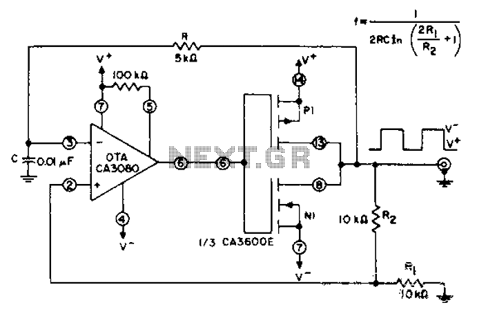
CA3600E array transistor pair and a reverse CA3080 operational amplifier are used together to provide precise timing and thresholds for the square wave. A typical static power consumption is 6mW. The CA3600E is a versatile integrated circuit that includes multiple...
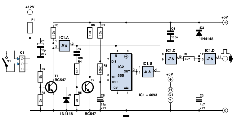
The circuit described here was designed as an addition to a remotely controlled garage door opener. The problem was that a brief burst of interference, arising from a thunderstorm or a mains spike, was enough to trigger the mechanism,...
This timer was designed primarily to switch off a portable radio after a set period. This feature allows users to fall asleep on the beach or in a hammock, knowing that the receiver will automatically turn off after a...
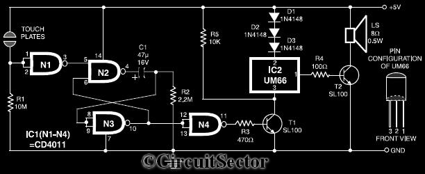
This circuit diagram illustrates a touch-sensitive musical bell based on the UM66 melody generator IC. The design incorporates a CMOS IC CD4011 and features a pair of touch plates. When these plates are briefly bridged by a hand, the...

This coil gun design utilizes arbitrary on/off times that are calculated based on the basic equations of motion, rather than chosen randomly. The coils do not activate at uniform intervals; the first coil remains energized for the longest duration...
A wide range auto turn OFF timer covering 1 minute to 20 hours in three ranges with S1. As soon as power is applied to the circuit, the IC1 [555] starts to oscillate and feeds clock pulses to the...
Warning: include(partials/cookie-banner.php): Failed to open stream: Permission denied in /var/www/html/nextgr/view-circuit.php on line 713
Warning: include(): Failed opening 'partials/cookie-banner.php' for inclusion (include_path='.:/usr/share/php') in /var/www/html/nextgr/view-circuit.php on line 713