
Sequential Actuator for powering up to four devices
There are various methods to implement this operation, but the described circuit is both simple and innovative. Rather than relying on an internal clock system, it utilizes an LM3914 integrated circuit designed to control the activation of 1 to 10 LEDs based on input voltage.
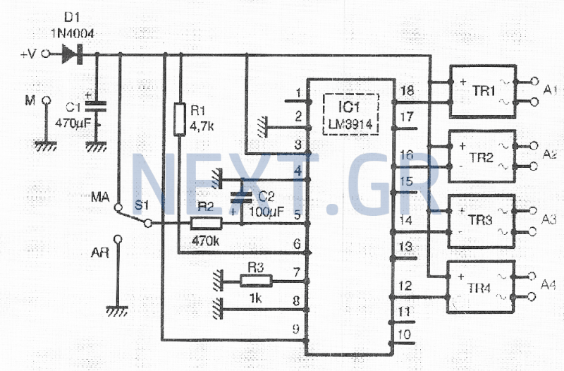
The LM3914, referred to as IC1 in the schematic, measures the voltage across capacitor C2, which charges slowly through resistor R2 once switch S1 is turned off. Consequently, the outputs of IC1 transition to a low potential sequentially, corresponding to the charging rate of C2. Instead of controlling a basic photodiode, these outputs operate photodiodes within optically coupled TRIACs or static relays (TR1 to TR4), which can handle up to 12A at 220V when necessary.
When switch S1 is off, capacitor C2 discharges through resistor R2, returning the outputs of IC1 to a high level, thus blocking TR1 and TR4. The total activation and deactivation time is determined by the R2/C2 configuration, which can be adjusted as needed. The power supply does not require stabilization and can operate from a feed block with an output voltage of 9V.
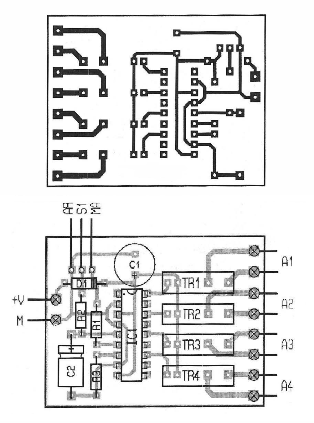
Although the circuit can control four devices, the printed circuit board (PCB) is compact. It is important to note that no space is allocated for heatsinks for TR1 to TR4. In applications such as high-fidelity audio systems or computer installations, these components will manage currents between 1A and 2A, negating the need for heatsinks. The components are generally easy to source, with the exception of TR1 to TR4.
Construction follows standard procedures, starting with passive components followed by active ones. The optocouplers TR1 to TR4 should be connected in series with the power supply of the devices they control. For simplified wiring, it is advisable to place them in parallel with the power switches of these devices. This arrangement allows for automatic operation in the switch-off position, with the option for manual activation by toggling the switch.
Given the presence of mains voltage at the terminals of TR1 to TR4, appropriate safety precautions must be taken, including housing the circuit in an insulated or grounded metal enclosure.
With the specified values for R2 and C2, the time taken for sequential activation of the devices is approximately 7 seconds, while the deactivation takes about 15 seconds. If a shorter duration is preferred, the values of R2 or C2 can be decreased. For example, using a 10μF capacitor for C2 can reduce the activation time to around 1 second and the deactivation time to approximately 1.5 to 2 seconds.
Components:
- IC1: LM3914
- TR1-TR4: S212S01 by SHARP
- D1: 1N4004
- R1: 4.7kΩ
- R2: 470kΩ
- R3: 1kΩ
- C1: 470μF / 25V
- C2: 100μF / 25V
- S1: On/Off switch
- IC socket DIL18It is common that sometimes we need to power some devices σuccessively one after the other. This function forces us to handle a large number of switches, which are located where the access is difficult, especially in the case of informational devices and their pipelines. This sequential actuator ensures by itself the activation of one to four devices in a specified order and a defined delay for each of them.
In the same way, it turns off the devices in the reverse direction of the ones that triggered them in the same automatic mode.
How does circuit work
There are many methods to construct this type of operation, but this circuit is simple and original. In fact, it does not use an internal clock system as expected, but an integrated circuit LM3914, which is designed to control the activation of 1 to 10 LEDs depending on its input voltage.
The LM3914, with the IC1 characteristic in Figure, measures the voltage displayed at the terminals of capacitor C2.
This capacitor is slowly charged through resistor R2, once the switch S1 is switched off. From this, the outputs of the integrated IC1 pass at low potential one after the other according to the charge rate of capacitor C2. Instead of controlling a simple photodiode, its outputs act on the photodiodes contained in optically coupled TRIACs or static relays, if desired, TR1 as TR4, whose outputs can control up to 12A at 220V, if necessary.
Since switch S1 is in the off position, capacitor C2 is discharged via resistor R2 and the outputs of the integrated IC1 return to the high level, which in turn blocks TR4 as TR1.
The total pause or activation time is set by the R2/C2 elements, which you can freely change according to your wishes. The power supply no need to be stabilized and can be left in a feed block whose output voltage is set to 9V.
Construction
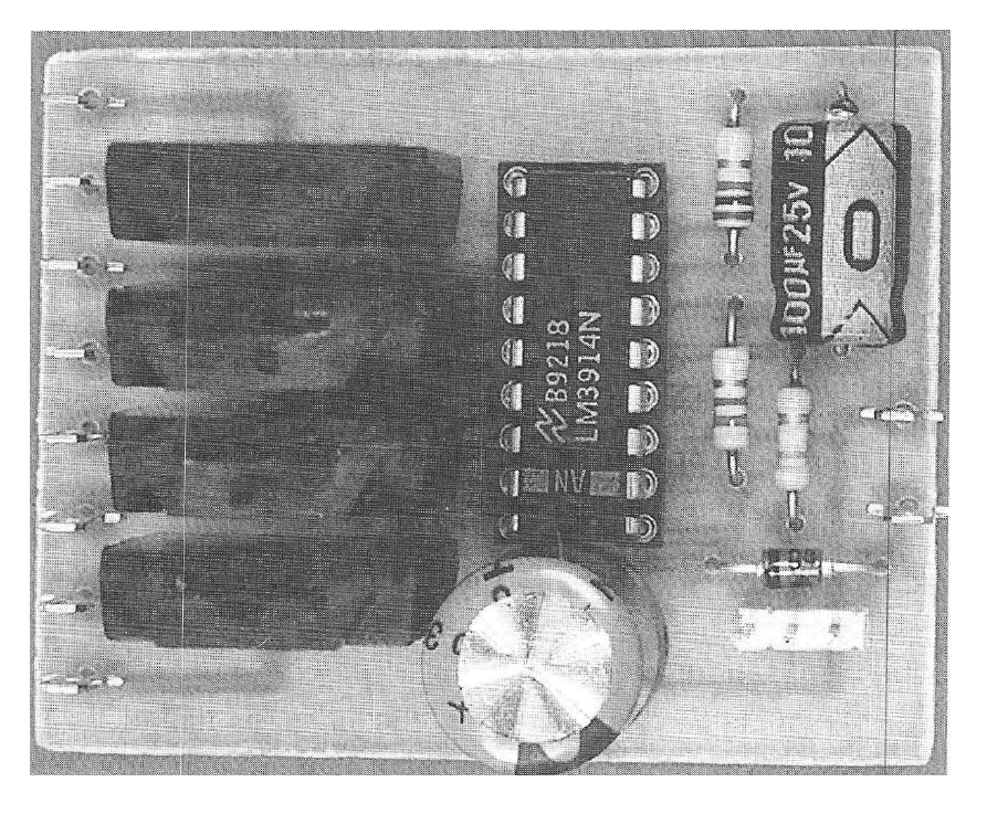
Although it can control four devices, the printed circuit (PCB) is extremely compact.
It should be noted that no space has been calculated for the TR1 to TR4 heatsinks. In fact, and for use in high-fidelity audio systems or for computer system installations, these components will control currents of 1A to 2A maximum. In this case they do not need any heat sinks. The components used do not pose any problems of finding, except for TR1 to TR4.
Construction will be done in the classic way.
First passive components and then active components. The optocouplers TRI as TR4 will be connected in series with the network supply of the devices they will control. To simplify the wiring, a good solution is to place it in parallel on the power switches of these devices.
In this way, in the switch-off position, the devices operate automatically and are driven by sequential activation, and if necessary, it is always possible to turn them on manually by switching the switch to the operating position.
Considering the presence of the grid voltage at the terminals TR1 to TR4, you should obviously take all the necessary precautions and the circuit will be placed in an insulated box or in a metal box that has been grounded.
With the R2 and C2 values, it takes about 7 seconds to switch between the sequential activations of the devices and about 15 seconds between successive device deactivations. If you think this is a long time, you can lower the value of R2 or C2 respectively. With a value of 10μF for capacitor C2 the time goes down in one second between each successive activation and about 1.5 to 2 seconds between each successive switch-off.
Components
IC1: LM3914
TR1-TR4: S212S01 by SHARP
D1: 1N4004
R1: 4.7kΩ
R2: 470kΩ
R3: 1kΩ
C1: 470μF / 25V
C2: 100μF / 25V
S1: switch on / off
IC socket DIL18
Related Circuits
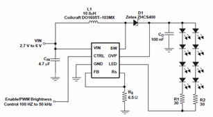
The schematic diagrams for the TPS61042 current LED driver illustrate its capability to power eight LEDs with an efficiency of 81% at 3.6V and 18.6mA. The TPS61042 is commonly utilized in applications such as white LED supply for backlight...
The timer circuit provides independent control over the output's on and off intervals, which can vary from 0.055 seconds to 30 minutes, and remains relatively unaffected by power-line transients. IC1 is a CMOS programmable timer chip that consists of...
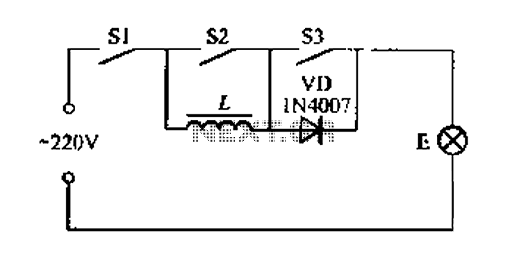
A portable four dimmer switch circuit is illustrated in Figure 8, featuring a four-speed brightness adjustment. When switches S1, S2, and S3 are all closed, the lamp operates at its brightest setting. When S1 and S2 are closed while...
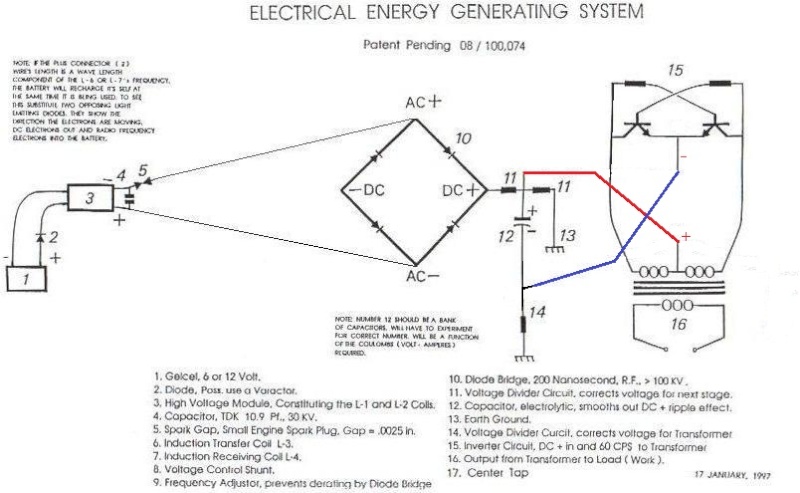
The natural resonant frequency of L2 is 31.5 MHz. The 40K value was calculated using an LC meter and LC resonance. The resonant frequency of an inductor-capacitor (LC) circuit is a critical parameter that determines its performance in various electronic...
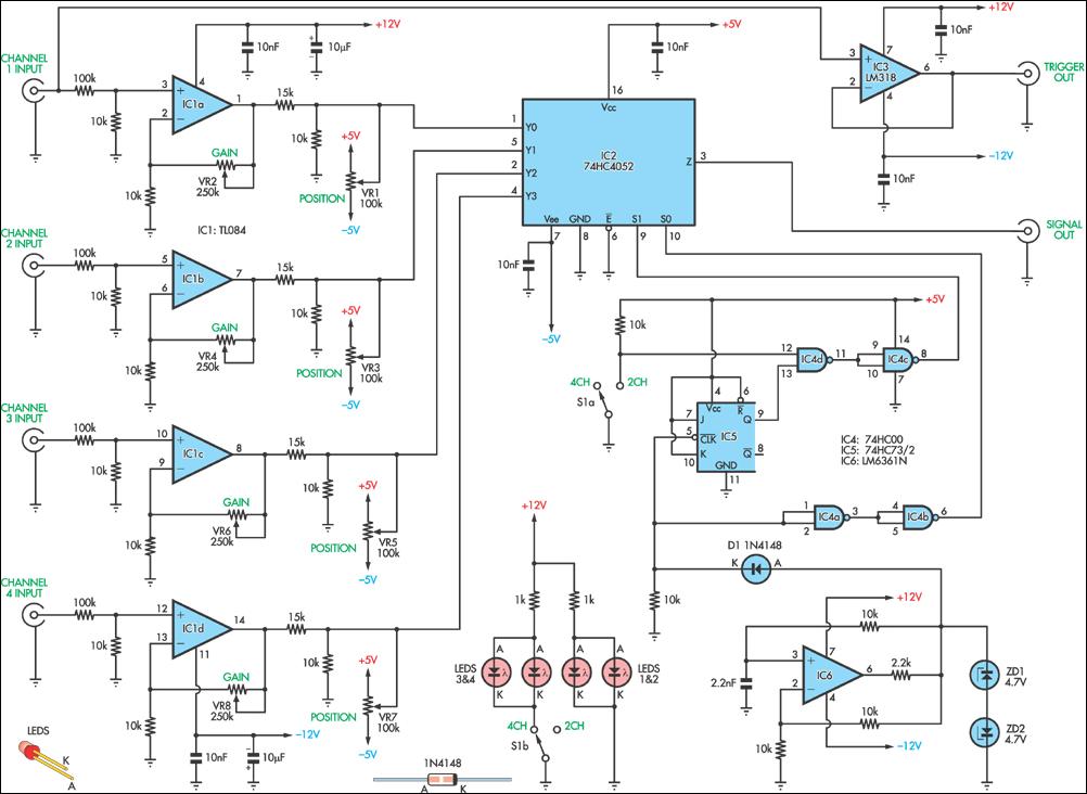
This circuit allows the simultaneous display of four signals using only one channel of an oscilloscope. It sequentially switches each input to the output while performing some signal conditioning. This configuration is designed for low-frequency signal measurements and lacks...
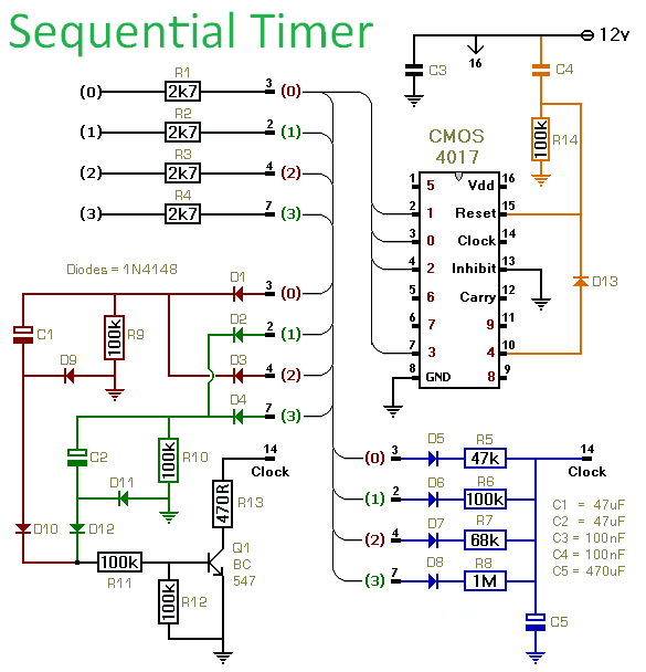
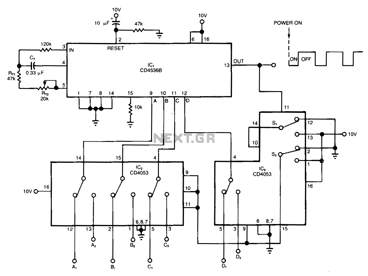
This circuit utilizes a CMOS 4017 decade counter to generate a sequence of four distinct events, with the capability to expand the sequence to nine or ten events. Each event's duration is independently controlled. The inclusion of D13 allows...