
Photo Switch Circuit
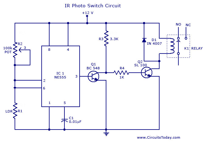
The circuit utilizes the NE555 timer IC configured in a comparator mode. The primary function of this circuit is to detect changes in ambient light levels and control a relay accordingly. The NE555 is a versatile integrated circuit capable of operating in various modes, and in this configuration, it serves as a light-dependent switch.
The circuit includes a light-dependent resistor (LDR), which changes its resistance based on the light intensity. When the light level falls below a predetermined threshold, the resistance of the LDR increases, causing the voltage at the non-inverting input of the NE555 to rise. This change in voltage triggers the output of the NE555, which activates the relay.
The relay acts as a switch that can control higher power devices, making the circuit practical for applications such as automatic lighting systems, security systems, or industrial automation. Additional components may include resistors to set the threshold levels, a potentiometer for fine-tuning sensitivity, and a capacitor to stabilize the circuit.
The schematic diagram typically illustrates the connections of the NE555, LDR, resistors, and relay, providing a clear visual representation of the circuit's functionality. This design is relatively straightforward, making it accessible for hobbyists and professionals alike who are looking to implement light-sensitive switching in their projects.A simple photo switch circuit using NE 555 IC with diagram and schematic.This photo switch ons a relay when light intensity crosses limit.A light sensor circuit for home and industrial purpose.. 🔗 External reference
Related Circuits
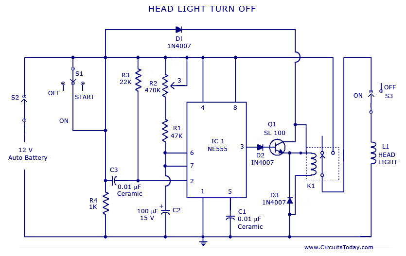
A circuit that can automatically turn off the headlights or lamps of a vehicle after a preset time. This light switching circuit is constructed using a 555 timer integrated circuit (IC). The described circuit utilizes the 555 timer IC in...
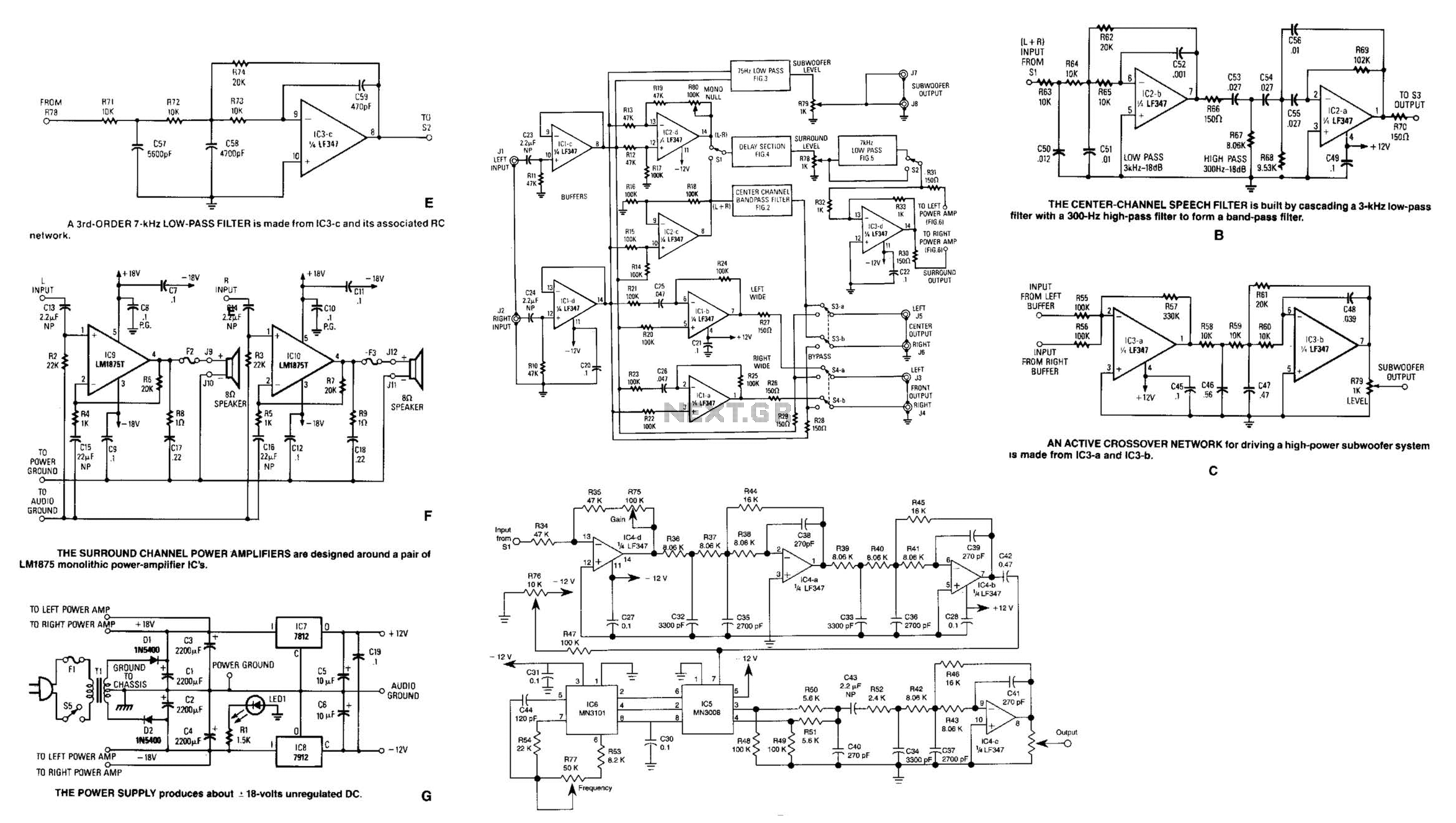
Referring to the simplified schematic in A, the audio frequency generator (AFG) consists of 10 relatively simple circuit elements. IC1-c and IC1-d are configured as unity-gain non-inverting buffer amplifiers. The summing amplifier, IC2-c, combines equal amounts of the left...
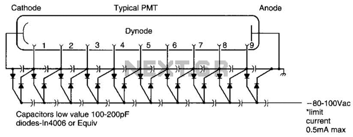
A Cockcroft-Walton voltage multiplier provides the necessary stepped voltage for the dynodes of the photomultiplier tube (PMT) without the use of a power-wasting voltage-divider resistor, which is typically employed in traditional configurations. The Cockcroft-Walton voltage multiplier is a type of DC-DC...
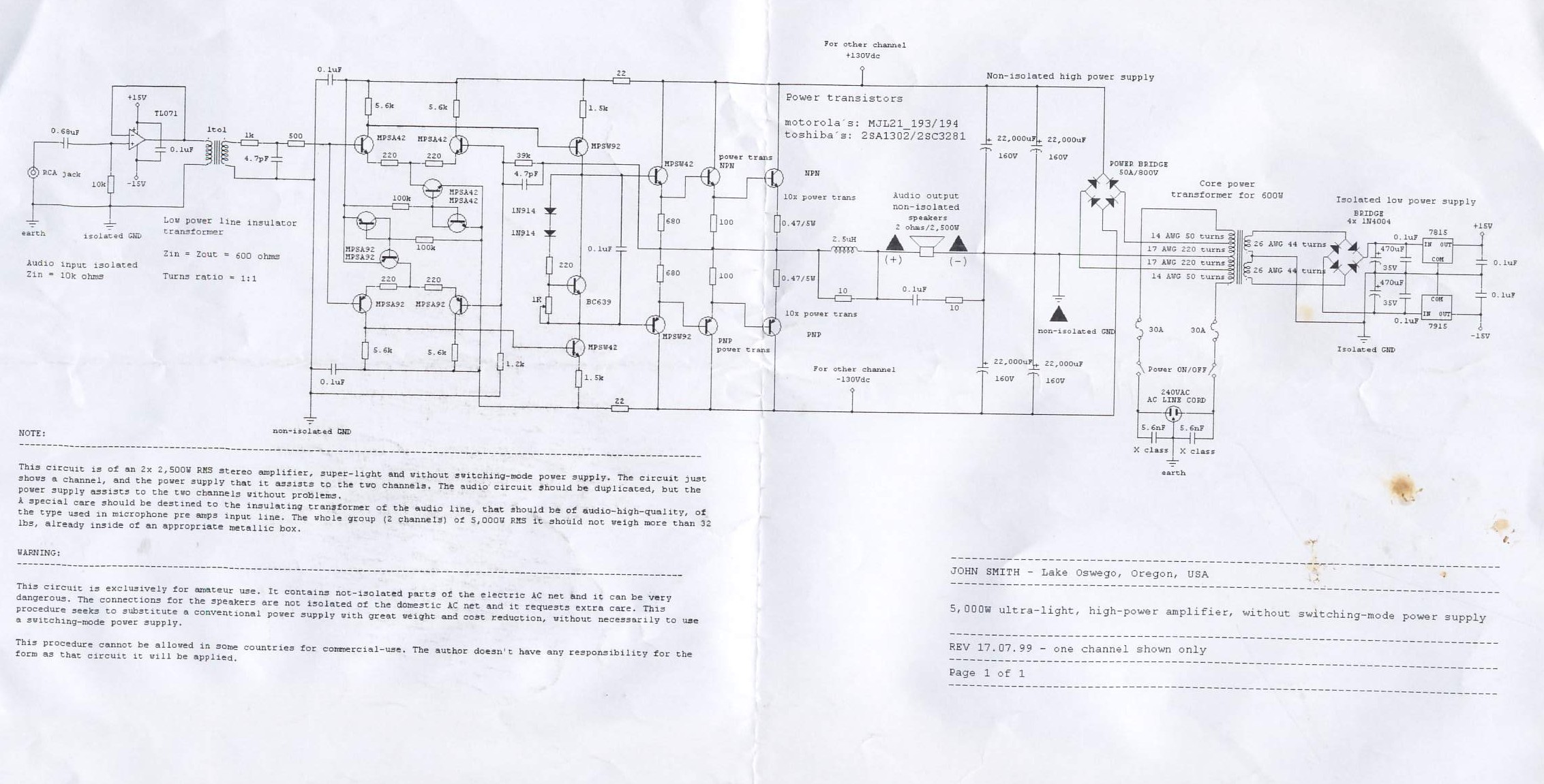
This circuit is for a 2x2, 500W RMS stereo amplifier that is super-light and does not utilize a switching-mode power supply. The circuit diagram displays only one channel, while the power supply is designed to support both channels. The...
It is well known that pests like rats, mice, etc., are repelled by ultrasonic frequency in the range of 30 kHz to 50 kHz. Human beings can't hear these high-frequency sounds. Unfortunately, all pests do not react at the...
This audio noise filter circuit is a bandpass filter designed for the audio frequency range. It effectively filters out unwanted signals that fall below or above the audio frequency spectrum. The audio noise filter circuit operates as a bandpass filter,...