
Automatic temperature control circuit
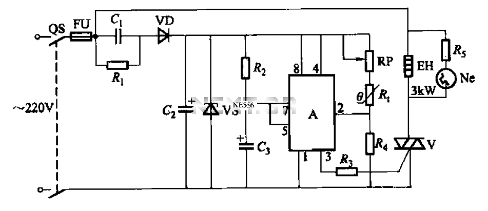
The operational analysis reveals that when the internal temperature falls below the preset threshold, the TRIAC (V) is activated by the output of the 555 IC, allowing current to flow to the electric heater (EH). As the internal temperature rises to the set point, the output from the 555 IC drops, turning off the TRIAC and halting the heater's operation, which is indicated by the neon bulb (Ne) extinguishing. Power is supplied to the 555 IC through a series of components: the AC voltage is reduced by capacitor C1, rectified by diode VD, and smoothed by capacitor C2 before being regulated to 12V DC. The 555 IC initiates a delay circuit; if the internal temperature remains below the set value, the thermistor's resistance increases, causing the output at pin 3 of the 555 IC to remain high, keeping the TRIAC conducting and the heater operational.
Once the temperature reaches the set point, the thermistor's resistance decreases, leading the output of the 555 IC to drop, which turns off the TRIAC and stops the heater. The internal discharge tube of the 555 IC short-circuits pin 7 to ground, discharging capacitor C3 in preparation for the next heating cycle. The cycle repeats as the internal temperature fluctuates, ensuring that the internal environment remains stable. The resistance (R1) and capacitance (C) play a vital role in discharging the circuit to prevent any residual voltage on capacitor C1 when power is cut, thereby reducing the risk of electric shock upon servicing the circuit. Automatic temperature control circuit shown in Figure 1-7, for climate control thermostat. (1) control purposes and methods of control objects: electric heater EH. Control purp oses: to make the temperature inside temperature constant. Control Methods: R. thermistor negative temperature coefficient As the temperature probe element and controlled with 555 IC. Protection components: fuse FU (heater overcurrent protection). (2) circuit O main circuit. By the switch QS, fuse FU, electric heater EH and TRIAC V (doubles as a control element) components. control circuit. By the 555 IC A, potentiometer RP, thermistor R., RC components monostable state triac trigger circuit and V components.
DC power. A capacitor Cl, Cz and diode VD and regulator vs composition. indicator. Neon bulb Ne (and current limiting resistor Rs) - electric heater EH heating instructions. (3) works O preliminary analysis. When the temperature inside the temperature drops below the set value, the heating should be a TRIAC V conduction --555 when the temperature inside the temperature was increased to the set value; 3 feet high output IC A group of should stop heating -v shut off a 3-pin output of a low level. down analysis. Power, 220V AC by capacitor Cl buck, half-wave rectifier diode VD, capacitor C2 after filtering and voltage regulator vs to 555 A integrated circuit provides 12V DC voltage.
At the same time set by the 555 A circuit composed of a delay circuit starts. If the temperature inside the temperature has dropped below the set value, the negative temperature coefficient thermistor resistance Rt greater potential A 2 foot by the RP, R. And R4 partial pressure of less than l/3Ee (4V) (Ec DC supply voltage 1ZV), A 3-pin output high (approximately 11V), Triac V trigger conduction, electric heater EH was electrically heated at the same time Ne neon bulb lights, said it is heated.
Since then monostable circuit into the transient, A internal discharge tube end, the discharge end 7 feet are vacant, the power to charge the capacitor C3 through the resistor Rz, 6 feet potential side threshold continuously rise higher about elapsed time t Fl. 1R2 C3,6 foot level can be increased to 2/3Ec (8V). If the temperature inside this time the temperature is still relatively low, that is, the trigger terminal 2 feet level is still lower than l/3EC circuit then remains set constant, continuous power supply plus electric heater EH heat; if the temperature reaches the set value has risen, due to the negative temperature coefficient thermistor R.
The resistance decreases with increasing temperature, then 2 feet higher than the level 1/3 Ee, 555 time-base integrated circuit reset monostable flip into a stable state, 3-pin output low (approximately ov ), Triac V off, electric heater EH stop heating, fluorine bubble Ne extinguished. At this time. 555 base integrated circuit inside the discharge tube is turned on, shorting 7 feet on the ground, so the charge stored in the capacitor C3 by 7 feet bleed, for the next time delay to prepare for heating.
When the temperature inside the temperature slowly decreases with time, and drops below the set temperature, Rt resistance and larger. A 2-foot level of the fork down to 1/3E. Hereinafter, the integrated circuit 555 is set again, flip the circuit into the temporary state, 3 feet high output, TRIAC V conduction, electric heater EH began heating, so repeat the cycle, from temperature to maintain the temperature inside constant.
The figure, the role of the resistance Ri is the capacitance C, providing a discharge circuit so that when you turn off the power, no voltage on Cl exist in, avoid touching the body capacitance of an electric shock.
Related Circuits
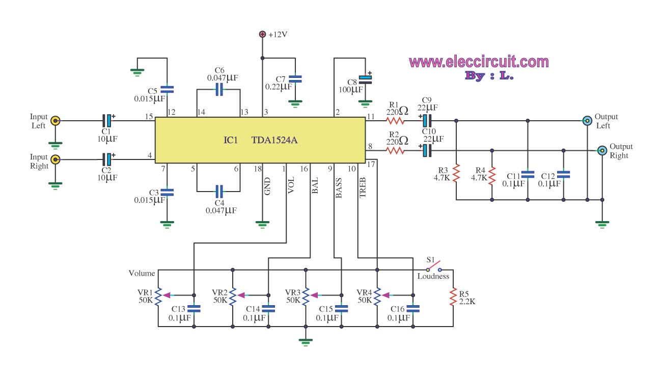
The stereo tone control circuit utilizes the integrated circuit TDA1524A. This IC serves as the central component in the design. The TDA1524A is a versatile integrated circuit designed for audio applications, particularly in tone control systems. It features a dual-channel...
Using this low cost project, one can reproduce audio from a TV without disturbing anyone. It does not use any wire between the TV and headphones. Instead of a pair of wires, it uses invisible infrared light to transmit...
The monostable 555 timer multivibrator circuit, also known as a one-shot monostable multivibrator, functions as a retriggerable pulse generator. The term "monostable" indicates that the circuit has only one stable state, with the unstable state referred to as the...
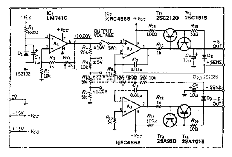
The maximum input voltage is 10V. An operational amplifier (op-amp) is used to provide a reference voltage of 10V, with its stability primarily determined by the characteristics of a temperature-compensated Zener diode (IS2192). The Zener voltage (Vz) can be...
This webpage outlines the radio transmitter unit that was part of the Cirrus One rocket mission in April 2001. The transmitter was included as a payload due to concerns about recovery challenges if the rocket drifted far downrange after...
This is a simple circuit for automatic switchover between battery and USB port. This circuit uses a more general step-up converter architecture. The circuit designed for automatic switchover between a battery and a USB power source employs a step-up...
Warning: include(partials/cookie-banner.php): Failed to open stream: Permission denied in /var/www/html/nextgr/view-circuit.php on line 713
Warning: include(): Failed opening 'partials/cookie-banner.php' for inclusion (include_path='.:/usr/share/php') in /var/www/html/nextgr/view-circuit.php on line 713