
Automobile and Electronic projects
The camera rotator circuit employs a 2716 EPROM to store a logic table that governs the motor driver (H-bridge) circuit. The EPROM data is represented in the schematic. Utilizing the EPROM eliminates the need for numerous discrete gates. The logic table allows the motor to rotate clockwise until the clockwise limit sensor is triggered, with similar functionality for counterclockwise rotation and its corresponding limit sensor. Inputs to the EPROM are derived from the limit sensors and two control switch directions. Outputs connect to the transistor gates of the H-bridge. The control switch signals are buffered through a 7400 quad NAND gate, accommodating long control wire runs. All input values are active in the low state. The H-bridge comprises two N-channel and two P-channel MOSFETs, with diagonal pairs activated to rotate the motor in either direction. If all transistors are off, the motor remains stationary. The P-channel transistors activate at a low logic output, while the N-channel transistors activate at a high logic output. Certain output states are prohibited; activating three or four transistors simultaneously could damage them. Proper programming of the EPROM should prevent such occurrences. A voltage regulator supplies 5V for the logic ICs and motor operation. A more advanced H-bridge driver circuit could be utilized for higher motor currents, although the current setup is adequate, simple to construct, and uses readily available components. A simpler circuit could be designed using a cross-wired center-off DPDT switch and mechanical limit sensors in series with the motor power wires, along with diodes across the switches. This configuration reduces moving parts and allows sensors to occupy less space than switches. The entirely solid-state design is expected to have a longer lifespan.
Two circuit boards are involved in this project, both hand-wired. The main board contains the logic circuitry and the VMOS FET array for the motor driver. It is constructed on a solderable breadboard. The hall effect sensor array is built on a copper PC board shaped like a 'C', with holes drilled for mounting to the motor. The two hall effect sensors are secured to the PC board with epoxy adhesive, and wire strain relief is necessary to prevent damage. Both sensors are positioned equidistant from the motor shaft's center. Other components on the sensor board are hand-wired to the sensors. The sensor board is mounted atop the motor, where the shaft exits the casing. A small, powerful magnet is affixed to the D-shaped aluminum block, passing directly over the hall effect sensors. The project requires significant mechanical work, with the camera and motor electronics housed within a Schedule 40 ABS black pipe. The upper section remains stationary and should be secured to an external mount using clamps. The upper portion includes a cap, a long tube for the motor and logic board, and an ABS sleeve glued to the bottom of the long pipe. Care should be taken to avoid glue on the sleeve's bottom half. The top cap connects to the upper pipe using a small screw, and an exit hole for the camera and motor control wires is drilled in the upper pipe. Once assembled, silicone caulk should seal the wire exit point to prevent moisture ingress. The lower pipe section houses the video camera, with the top inch filed for a snug fit into the upper sleeve. A hole is created for the camera, and the camera is secured with packing foam. A cap covers the lower assembly's bottom, and the camera wire should be routed internally, ensuring it does not snag. Consideration for water flow is essential; the assembly must withstand rain without compromising the electronics. A small hole in the lower cap allows condensation to escape.
Various metal components must be fabricated, including a bracket to attach the motor mount to the upper tube, with the size contingent on the motor used. The motor shaft must be centered within the tube upon completion of the mount. The shaft mount is a D-shaped aluminum piece with a hole for the motor shaft and a side hole for a set-screw. Two holes are drilled and tapped into the mount for securing screws. The magnet is glued to the shaft mount, ensuring it passes over the hall effect sensors. The camera wire length must allow for slack during movement, and sharp edges should be rounded to prevent damage to the wire. The camera should rotate counterclockwise upon switching to CCW until the limit is detected, and similarly for clockwise rotation. When the switch is off, the camera should remain stationary. The project utilizes surplus parts, including a 12V gear reduction motor by Globe. Electronic components are available from suppliers such as DigiKey. Compact video cameras are now affordable, and small televisions can be sourced from online auction platforms. This enables the construction of a miniature short-range wireless video system using off-the-shelf components. However, this wireless circuit is not suitable for long-distance operation; the video modulator interfaces the video signal to a standard TV, with transmission limited to a few feet. A 12V DC supply powers the camera and video modulator circuits, with the camera's video output connected to the modulator's input. The modulated RF output connects to a small antenna. A dipole antenna resonant at the modulator's frequency can enhance signal range. For longer wired operation, the RF signal can be routed through 75-ohm coaxial cable, with a terminating resistor at the far end. The cable's center conductor connects to the TV antenna through a 330-ohm resistor. Powering the camera and modulator requires careful attention to polarity to avoid damage; some devices include reverse polarity protection. The modulator's RF output connects to a small antenna, which can be constructed from short lengths of #16 gauge solid wire. For optimal operation, the appropriate AC adapter should be used for the Watchman TV. If battery operation is preferred, the TV can run on internal batteries while the camera and modulator are powered by a 12V battery. A rechargeable lead-acid battery with a series fuse and recharging circuit is recommended. This system could serve as an engineer's view of a model train layout, utilizing a wire loop near the track as a receiving antenna, with power sourced from the engine motor circuit through a bridge rectifier and capacitor, ensuring the camera's maximum voltage is not exceeded.This is an 8-input x-output audio/video switch module to be controlled from a computer, for example from the parallel port. Each audio/video output can be switched to any of the 8 inputs, separately. One module drives one audio/video output and has a 34-pin connector to plug into the system interface.
You can use video OPA-s on the 4051 output inst ead. Note that you can get full integrated video multiplexers from Maxim. The first 74LS00 gate acts as a buffer for the input logic pin. The following gates invert the signal, then further buffer it for driving the High and Low LEDs. The first 74LS123 one shot stretches out low going pulses so that they blink the Low Pulse LED for a long enough time to be visible. The second 74LS123 does the same thing for high going pulses. This circuit can be built on perforated circuit board and wired by hand. The completed circuit can be assembled into a clear plastic box with the wires protruding out one end.
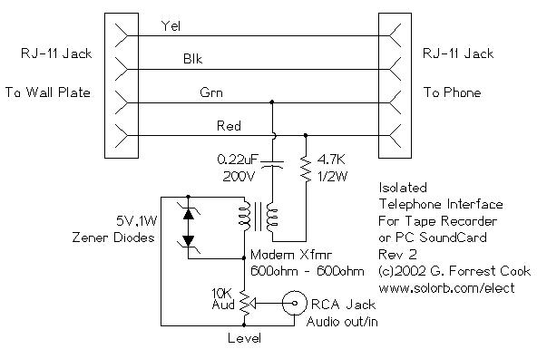
The LEDs should be visible through the box. IC sockets should be used for easy chip replacement. Clip the probe`s ground and +5V lead to the ground and +5V rails on the logic circut under test. Connect the probe lead to the logic lines that you wish to examine. The High and Low LED indicators indicate high and low logic levels. A single high pulse will cause the High Pulse LED to light, and A single low pulse will cause the Low Pulse LED to light. A square wave or repeating pulse waveform will cause both the High and Low Pulse LEDs to light. This circuit allows you to record audio from a telephone line into a tape recorder or computer soundcard.
Most of the parts for this circuit can be scrounged from an old modem, with some work, it is possible to rewire the modem circuitry and use the old modem case. Note that some countries have laws that require the user of a phone recording device to notify the party on the other end of the line that they are being recorded.
There`s not much to this circuit. The two RJ-11 jacks are set up to feed the telephone circuit through from the wall to the phone. The active signal for a single phone is on the red and green wires. Yellow and black are usually used for a second phone line. The 0. 22uF capacitor blocks any DC current from flowing through the transformer. The 4. 7K resistor limits the current of the 90V ringing signal. The transformer isolates the telephone side of the circuit from the tape recorder side. The zener diodes clamp the 90 volt ringing signal and other transient spikes to protect your recorder. The 10K potentiometer is used to adjust the level to the tape recorder. Using two RJ-11 phone line jumpers, connect one side of the interface to the wall plate and the other side to a telephone.
Connect the audio out to a tape recorder or PC sound card`s auxilliary input. Set the recording level and start recording. It should also be possible to inject an audio signal into the audio output jack and have it appear on the phone line, the level control should be all the way up, drive the circuit from an amplifier that is capable of running a small speaker. 2X RJ-11 phone Jacks 1X 0. 22uF 200V capacitor 1X 4. 7K 1/2W resistor 1X 600 ohm to 600 ohm modem transformer 2X 5V 1W zener diodes 1X 10K audio taper potentiometer 1X RCA audio jack The camera rotator circuit uses a 2716 EPROM to store a table of logic values that control the motor driver (H-bridge) circuit.
The EPROM data is shown in the schematic. By using the EPROM, a large number of discrete gates are eliminated. The logic table is designed to allow the motor to turn clockwise until the clockwise limit sensor is activated. The same operation happens with counter clockwise rotation and the counter clockwise limit sensor. Inputs to the EPROM come from the limit sensors and the two control switch directions. Outputs go to the four H-bridge transistor gates. The control switch signals are buffered through the 7400 quad NAND gate, this allows for a long control wire.
All of the input values are active in the low state. The H-bridge array consists of two N-channel MOSFETs and two P-channel MOSFETs. Diagonal pairs of transistors are turned on to move the motor one way or the other. If all of the transistors are off, the motor does not move. Note that the P channel transistors turn on with a 0 logic output level and the N channel transistors turn on with a 1 logic output level. There are several disallowed output states, if three or four transistors were to be turned on, the transistors would go up in smoke.
Don`t do this. If the EPROM is programmed correctly, this should never happen. The voltage regulator produces 5 volts for running the logic ICs and the motor. A better H-bridge driver circuit (or IC) could be used if higher motor currents are needed, this one was sufficient, simple to build, and easy to find parts for. Note that a much simpler version of this circuit could be made by using a cross-wired center off DPDT direction switch and mechanical limit sensor switches in series with the motor power wires and with diodes across the switches.
This circuit has fewer moving parts, and the sensors can fit into a smaller space than switches. The all solid state design should also last longer. There are two circuit boards in this project, both were hand-wired. The main board houses the logic circuitry and the motor H-driver VMOS FET array. It was constructed on a solderable bread-board. The hall effect sensor array was built on a piece of copper PC board. The board was cut to a C shape and holes were drilled in the ends so that the board could be screwed to the motor mount tabs. The two hall effect sensors were glued to the PC board with epoxy glue. Be sure to secure the wire coming from the sensor board with some form of strain relief. Plastic wire ties are suitable for this job. Both sensors are located an equal distance from the center of the motor shaft. Other sensor board components were hand-wired to the sensors. The sensor board can be seen in the photo, it is mounted on the top of the motor where the shaft exits the motor case.
The D-shaped aluminum block has a small, but powerful magnet glued to the side that passes directly over the hall effect sensors. The magnets pass within about 1/8 inch over the sensors. This project involves a fair amount of mechanical work. The tube that holds the camera, electronics, and motor was fabricated with Schedule 40 ABS black pipe.
The longer portion (top) of the pipe is stationary, and should be secured to an external mount with hose clamps or other mounts. The top portion consists of a cap on top, a long tube with room for the motor and logic board, and an ABS pipe sleeve.
Glue the sleeve to the bottom of the long pipe. Don`t get any glue on the bottom half of the sleeve. The top cap can be connected to the upper pipe by drilling a small hole through the cap pipe, and installing a small stainless steel screw. A small hole is drilled through the upper pipe, this allows the video camera and motor control wires to exit the assembly.
When the assembly is complete, seal the wires where they exit with Silicone caulk. The small, lower portion of the pipe houses the video camera. The top inch of the lower portion should be evenly filed around the outside so that it can be fitted easily into the top portion`s sleeve. Keep filing until the lower portion of the pipe spins easily in the sleeve. A hole needs to be cut in the lower portion to house the camera. This can be done by drilling small holes, then filing the opening until the camera fits snugly. The hole should be large enough to allow the camera to be adjusted up and down. I secured my camera in the lower assembly with blue packing foam. A pipe cap covers the bottom of the lower assembly. The camera`s wire should pass through the inside of the tube, put a few loops of extra wire on the camera side.
It is important to verify that the wire does not get hung up on any objects in its path. Water flow should be considered, if the assembly is built correctly, it should be able to withstand blowing rain without getting the electronics wet. A small hole should be drilled in the lower pipe cap to allow any moisture that condenses inside to escape.
Several metal pieces need to be fabricated. A small bracket is needed to connect the motor mount to the side of the upper tube. The size of the bracket depends on the motor that is used. The motor shaft should be exactly centered in the tube when the mount is complete. The shaft mount piece is a D-shaped chunk of aluminum, a hole was drilled to fit the motor shaft, a side hole was drilled and tapped to hold a set-screw for securing the mount to the shaft. Two mount holes were drilled and tapped into the mount, screws pass through the lower pipe into the mount.
The magnet is glued to the bottom of the shaft mount, it should pass right over the hall effect sensors. Test the magnet on the hall effect sensors before gluing them in place, the sensors only respond to one side (pole) of the magnet.
Make sure that the camera wire does not get hung up on the insides of the camera, this is achieved by adjusting the length so that the wire has some slack when it is at either extreme of the movement. It is advisable to round any sharp edges that are in the area where the video wire rotates. Turn the switch to CCW, the camera should rotate couter clockwise until the limit is sensed. Turn the switch to CW, the camera should rotate clockwise until the other limit is reached. Turn the switch off, the camera should stand still. This project was built with surplus parts. The motor is a 12 Volt gear reduction unit made by Globe. The electronic components can be found at DigiKey (1-800-DIGI-KEY). Incredibly small video cameras have recently become available at reasonable prices. Small televisions are available for very little money at online auction sites such as eBay. It is now possible to build a miniature short-range wireless video system with off-the-shelf parts. This wireless nature of this circuit is not suitable for long distance operation, the video modulator just provides a simple method for interfacing the video signal to a standard TV.
Transmission distance is limited to a few feet. The 12VDC supply provides power for the camera and video modulator circuits. The video from the camera is fed into the video input of the modulator circuit. The modulated RF from the modulator is fed into a small antenna. Use of a dipole antenna that is resonant at the frequency of the modulator can extend the signal range. The RF travels across a short distance to the Sony Watchman TV receiver. A black and white image magically appears on the TV screen. The camera`s video signal is connected to the video modulator with an RCA jumper cable. Power to the camera and video modulator is connected to the 12V power supply. Be careful with polarity, reversing the leads may damage the modulator. The camera that was used had reverse polarity protection built in. The modulator`s RF output signal is connected to a small antenna, the antenna can be made with two short lengths of #16 gauge solid wire.
Alternately, for long distance wired operation, the RF signal can be fed into a length of 75 ohm coax cable with a 75 ohm terminating resistor across the far end of the cable. Connect the remote center conductor of the cable to the TV antenna through a 330 ohm resistor. Turn the power for the camera and modulator on, turn on the TV. Tune the TV to the channel of the RF modulator, fine-tune the TV for the best picture. For full-time operation, use the appropriate AC adapter for the watchman. If battery operation is desired, run the TV from its internal batteries and use a 12V battery for powering the camera and modulator.
A rechargeable lead acid battery with a series fuse (and a recharging circuit) is recommended. A fun use for this system would be to create an engineer`s view of a model train layout. A loop of wire near the track would make a good receiving antenna. Power could be pulled from the engine motor circuit using a bridge rectifier feeding into an electrolytic capacitor, just make sure not to exceed the camera`s 12V maximum supply voltage. Tired of always spending money on flashlight batteries only to have them fail just when you need them Try this simple circuit out.
It would make an excellent science fair project. The white LEDs are quite bright, they provide enough light to illuminate a small room at night. The LEDs produce a nicely focused beam. You can read by the light of this device. The red, orange, yellow and green LEDs broaden the lamp`s color spectrum to produce a slighly warmer color temperature. The box also doubles as a 12V power source and can run other small loads such as a transistor radio. 🔗 External reference
Related Circuits
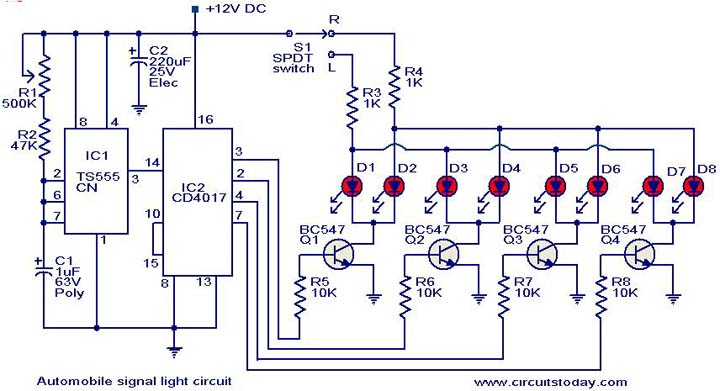
This is a simple circuit that can be used as a sequential signal light in automobiles. The circuit is based on two integrated circuits (ICs): a TS 555 CN CMOS timer IC and a CD4017 decade counter IC. The...

The circuit is a high-power car audio amplifier schematic. It functions as a car audio amplifier using the PA02 and LH0101 integrated circuits (ICs). Each IC delivers an output power of 30W with an 8-ohm impedance. The part list...
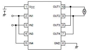
A simple forward-reverse motor control driver electronic circuit can be designed using the LB1948M, a two-channel low saturation voltage forward-reverse motor control driver IC. The LB1948M motor driver is suitable for use in 12V system products and can drive...
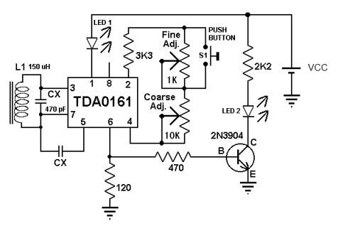
This metal detector circuit diagram utilizes the TDA0161 monolithic integrated circuit, which is designed to detect metallic objects by measuring variations in high-frequency Eddy current losses. The output signal is influenced by changes in supply current, which varies based...
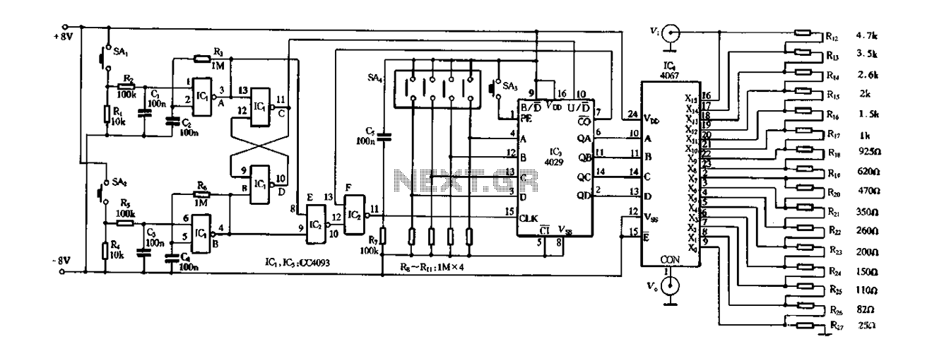
Figure 4-14 illustrates a digital integrated circuit featuring 16 preset potentiometers for Siniperca electronic circuits. The circuit comprises three main components: an input controller, a presettable counter, an analog electronic switch, and a resistor network. It includes a push-button...
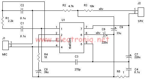
A very simple audio amplifier circuit can be designed using the TBA820M audio amplifier integrated circuit with just a few electronic components. This audio amplifier project features a high gain that allows for the detection of sounds underwater. The...