
Automotive Audible-Turn Indicator Circuit
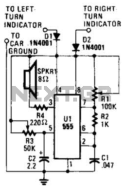
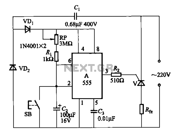
The circuit operates by monitoring the state of the turn indicator lights, which are typically controlled by a relay or a direct connection to the vehicle's lighting system. When the turn indicator is activated, a signal is sent to the tone generator circuit. This circuit can consist of a simple oscillator, such as a 555 timer configured in astable mode, which produces a square wave output.
The frequency of the output tone can be controlled by varying the resistor and capacitor values in the timing circuit. To achieve the desired effect of a decreasing frequency, a feedback mechanism can be implemented. This can be accomplished by integrating a capacitor that gradually discharges while the indicator is lit, effectively lowering the frequency over time.
Additionally, a transistor can be used to amplify the tone output, ensuring it is audible even in noisy environments. A small speaker or piezo buzzer can be connected to the output of the transistor, providing a clear sound that alerts the user when the turn indicator is active.
Power for the circuit can be drawn from the vehicle's battery, with appropriate voltage regulation to ensure safe operation of the electronic components. A diode may be included to protect against reverse polarity connections.
This circuit not only enhances safety by providing auditory feedback for turn signals but also caters specifically to the needs of those with hearing impairments, allowing for a more inclusive driving experience. This little circuit should be useful to the hearing impaired. It produces a tone each time a dashboard turn indicator lights. The tone drops in frequency for as long asthe indicator is lit. 🔗 External reference
Related Circuits
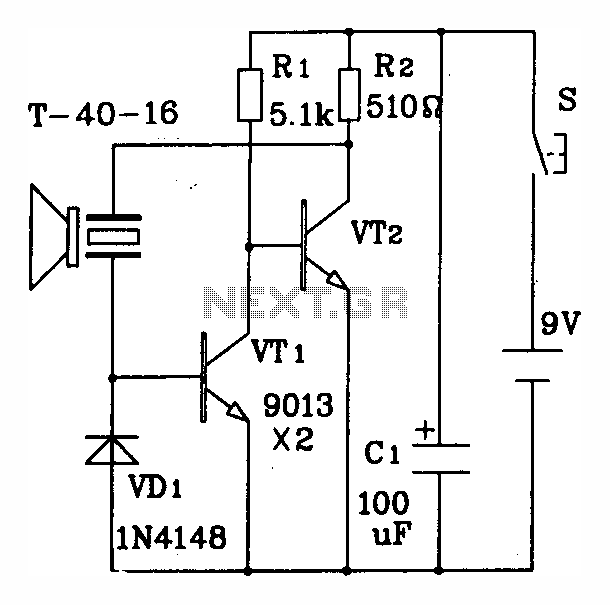
The discrete components ultrasonic transmitting circuit T/R-40-16 is capable of emitting a series of ultrasonic signals at a frequency of 40 kHz. This circuit operates at a voltage of 9V, with an operating current of 25 mA, and can...
This circuit utilizes an LM339 quad voltage comparator to create a time delay and manage a high current output at low voltage levels. Approximately 5 amps of current can be achieved using two fresh alkaline D batteries. Three of...
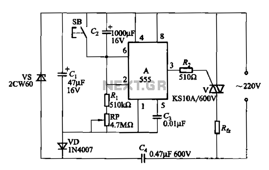
The circuit utilizes a 555 Integrated Circuit (IC) configured as a delay circuit. It transitions from a low to a high state after a button (SB) is pressed, initiating a delay before the output terminal goes high. The output...
Locker Guard Circuit Diagram. This compact circuit is designed to protect a locker or almirah from burglary. If the locker is opened while in the armed state, the circuit triggers a loud police siren to deter the burglary attempt. The...
The 555 integrated circuit (IC) is utilized in a delay circuit configuration. It transitions from a high to a low output state when a button (SB) is pressed. The output remains high for a specified delay period before transitioning...
This cable TV amplifier circuit is an RF amplifier designed for quick installation between two coaxial cables. Both the input and output impedances are compatible with 75-ohm cables. The main amplifier is the T1 transistor, while T2 functions as...
Warning: include(partials/cookie-banner.php): Failed to open stream: Permission denied in /var/www/html/nextgr/view-circuit.php on line 713
Warning: include(): Failed opening 'partials/cookie-banner.php' for inclusion (include_path='.:/usr/share/php') in /var/www/html/nextgr/view-circuit.php on line 713