
Automotive Check Engine Light Diagnosis

The electrical system in contemporary vehicles is complex and often requires specialized knowledge to diagnose and repair effectively. This guide encompasses various aspects of electrical diagnostics, including understanding the onboard diagnostics (OBD) system, interpreting fault codes, and utilizing diagnostic tools such as multimeters and oscilloscopes.
Key components of the electrical system that may be tested include the battery, alternator, starter motor, and various sensors and actuators. The guide outlines methods for testing these components, including voltage and resistance measurements, as well as the use of scan tools to retrieve and analyze trouble codes.
Additionally, troubleshooting strategies are provided for common issues that trigger the check engine light. This includes checking for loose or damaged wiring, inspecting fuses, and ensuring that all connectors are secure. The importance of following manufacturer-specific diagnostic procedures and utilizing service manuals is emphasized to ensure accurate and effective repairs.
Overall, this guide is designed to equip technicians and vehicle owners with the knowledge necessary to navigate the complexities of automotive electrical systems, thereby facilitating timely and efficient repairs while minimizing the risk of further complications.A complete guide to tackling those difficult electrical system tests in today`s cars. The ultimate resource for getting rid of that check engine light! Get info from a professional technician today!.. 🔗 External reference
Related Circuits
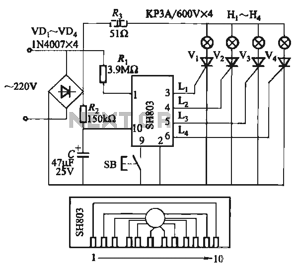
The circuit utilizes the SH803 flash IC, which can store eight different programs and offers various dimming options and light speed adjustments. A button is provided to trigger the control terminal SB on the 9-pin connector for program selection,...

This page features a circuit that has twenty open collector outputs that turn on one at a time in a continuous sequential manner. The circuit utilizes the 74LSxx family of TTL integrated logic devices. The circuits are designed to...
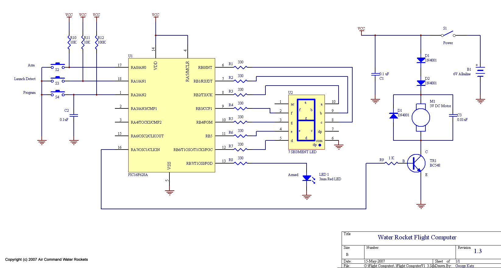
The design modifications were primarily selected to enhance the system's weight efficiency. The majority of weight reduction was achieved through the implementation of a single board design, transitioning to single battery operation, and directly mounting the battery onto the...
The circuit utilizes a 555 timer integrated circuit (IC) configured as an astable multivibrator. The flashing rate can be adjusted from very fast to a maximum of once every 1.5 seconds by changing the setting of the preset variable...
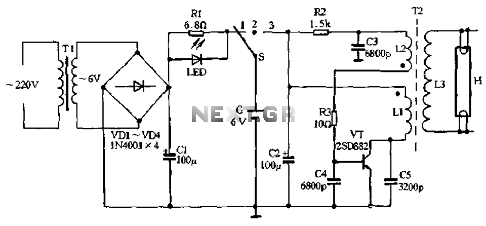
The charging circuit comprises a transformer (Tl), diodes (VDI-VD4), and various additional components. It operates on 220V AC, with the transformer Tl stepping down the voltage, while diodes VDI-VD4 perform rectification. A smoothing filter (CI) converts the rectified output...
Using high-beam headlights while driving on the highway can significantly enhance visibility; however, they may pose a blinding risk to other drivers. This straightforward circuit can be integrated into the headlight switch to enable automatic switching between high and...