
Blackout emergency lights 4

The charging circuit is designed to efficiently convert AC mains voltage into a usable DC voltage for battery charging applications. The transformer Tl steps down the high-voltage AC input to a lower AC voltage, which is then rectified by diodes VDI-VD4 to produce a pulsating DC voltage. The smoothing filter (CI) typically consists of capacitors that help to flatten the pulsating DC output, ensuring a stable voltage level for the battery charging process.
The function selector switch (G) allows the user to select different operational modes, including a charging mode and an emergency lighting mode. In the charging mode, the resistor (Rl) limits the charging current to prevent overcharging, while the LED indicator provides a visual cue of the charging status. When the battery is sufficiently charged, the LED indicator turns off, indicating that the charging process can be safely terminated.
In emergency lighting mode, the circuit utilizes a feedback oscillator formed by the triode (VT) and transformer coils (L1, L2) along with capacitors (C3-C5). This configuration generates a high-frequency oscillation that is transformed into a higher voltage by the boost coil (L3). The resulting voltage is applied to the fluorescent tubes (H), providing illumination in emergency situations. The design ensures that the circuit can quickly switch between charging and lighting modes, making it versatile for various applications. The overall layout and component selection are critical for achieving efficient operation and reliability in both charging and emergency lighting functionalities. Charging circuit by the transformer Tl, diode VDI-VD4 and other components, 220V AC by Tl buck, VDI ~ VD4 rectification, CI smoothing filter into DC power to charge the battery G provided. S for the function selector switch position shown for the state of charge, when the DC voltage to charge the battery via a resistor Rl G. LED charging indicator light emitting tube, when the reservoir after sufficient battery G, because the charging current is reduced, the voltage drop across Rl also decreases insufficient to maintain the LED has turned on, LED will automatically turn off, indicating that G is fully charged.
When 3:00 s dial switch to the position for the emergency lighting state. Triode VT, 1r2 boosting transformer coil L1, L2 and a capacitor C3 ~ C5 composition inductance feedback oscillator, an oscillating voltage applied directly after the boosted boost coil L3 to fluorescent tubes H both ends of the excitation lamp H light. When the switch to the position 2, is turned off.
Related Circuits
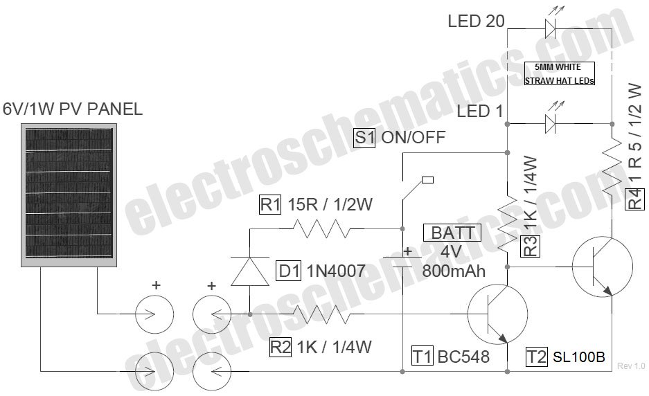
The circuit for the LED solar lantern lights is designed using a 6V/1W solar panel (photovoltaic panel) and a 4V/800mAh lead-acid battery. The schematic for the LED solar lantern circuit incorporates a solar panel that converts sunlight into electrical energy....
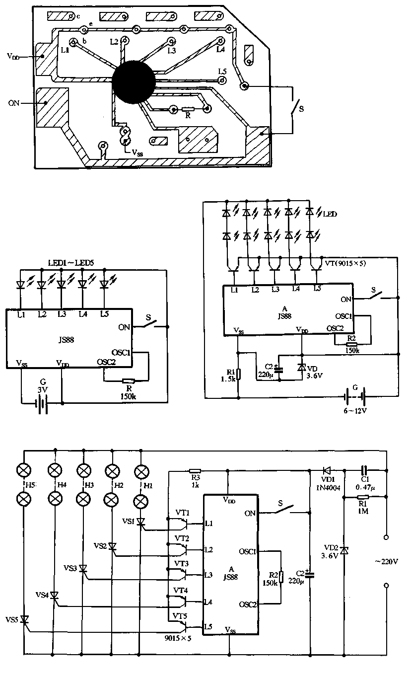
Figure 2-39 illustrates a typical application circuit for the JS88 manifold, which includes an oscillation resistor (R) that allows for fine-tuning of the water flicker frequency. When switch (S) is closed, components L1 to L5 sequentially output low signals...
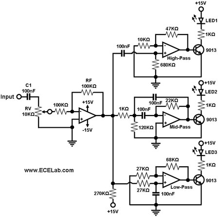
The simple circuit for converting an audio signal. The circuit basically consists of a buffer/amplifier stage and three filter circuits. The audio signal conversion circuit is designed to process audio signals efficiently while maintaining signal integrity. The circuit architecture includes...
The charging circuit automatically stops when the battery is fully charged, allowing the emergency light to remain connected to the AC mains overnight without concern. The circuit is divided into two sections: the inverter and the charger. The inverter...
The circuit comprises two sections: charger power supply and LED driver. The charger power supply section is built around a 3-terminal adjustable regulator (IC1) LM317, while the LED driver section is built around transistor BD140 (T2). In the charger...
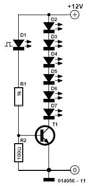
This simple and inexpensive circuit is not limited to Christmas. It consists of two resistors, a small-signal transistor such as a BC547, one flashing LED, and a string of standard LEDs. The flashing LED functions as an oscillator, turning...