
Automotive Electrical Tester
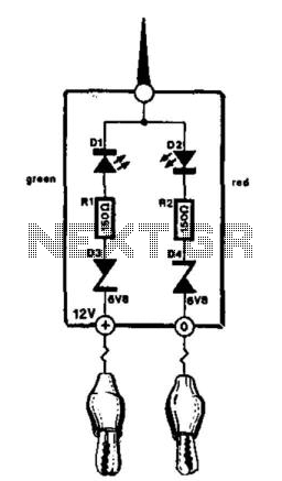
The vehicle electrical circuit tester is a practical tool for diagnosing electrical issues in automotive systems. The device consists of an enclosure housing the necessary electronic components, including two LEDs that provide visual feedback about the circuit status. The red LED illuminates when the positive supply line is detected, while the green LED lights up when a ground connection is established.
Powering the tester directly from the vehicle's battery ensures that it operates at the correct voltage level, which is crucial for accurate measurements and functionality. The use of insulated heavy-duty crocodile clips enhances safety and reliability, allowing the user to make secure connections to the battery terminals or fuse box without the risk of short circuits or accidental disconnections.
For convenience, the tester can also be fitted with a connector compatible with the vehicle's cigarette lighter socket, providing an alternative method for powering the device. This versatility allows for easy access to power in various scenarios.
In instances where it is necessary to test insulated wiring, the inclusion of a sharp needle soldered to one of the terminals is particularly beneficial. This feature allows the user to pierce the insulation of wires carrying 12 V, enabling circuit testing without compromising the integrity of the insulation. The design ensures that while the needle penetrates the outer layer, it does not damage the wire itself, maintaining the overall functionality of the electrical system.
Overall, this vehicle electrical circuit tester is an essential tool for automotive technicians and DIY enthusiasts alike, providing a straightforward solution for diagnosing electrical issues in a safe and effective manner. This little tester is useful for checking vehicle electrical circuits. Two LEDs indicate whether one of the cl ips is connected to the positive supply line (red) or to ground (green). The unit is powered by the vehicle battery. It is advisable to terminate the unit into two insulated heavy-duty crocodile clips. These enable connection to be made directly to the battery or to terminals on the fuse box.It is also possible to terminate it into a suitable connector that fits into the cigarette lighter socket. If a sharp needle is soldered to one of the terminals, it is possible to check insulated wiring—but only those that carry 12 V.
Although the needle pierces the insulation, it does not damage it. 🔗 External reference
Related Circuits

The electrical system of the 2005 Yamaha DT125X typically includes a CDI unit, battery, thermo unit, rectifier/regulator, servomotor, fuse, neutral switch, ignition coil, and main switch. The electrical schematic for the 2005 Yamaha DT125X outlines the interconnections and functionalities...

Camping today often requires bringing various electronic devices for daily use or entertainment. Typically, a charged lead-acid battery and a power inverter are utilized to ensure a well-organized holiday where family members can enjoy their electronic gadgets. It is...

The tester provides an audible indication, eliminating the need for the user to directly observe a meter reading. Additionally, the current and voltage output of the tester are strictly limited, with a maximum of 0.6 volts DC and 3...
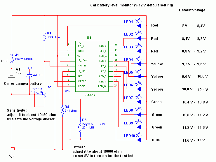
This circuit utilizes the widely available LM3914 integrated circuit (IC). The LM3914 is straightforward to operate, does not require external voltage regulators due to its built-in voltage regulation, and can be powered from nearly any voltage source. This makes...

The circuit biases the BC558 transistor, causing LED D1 to flash in response to signals from the remote control. The preset resistor in the circuit sets the sensitivity level. The circuit utilizes a BC558 PNP transistor, which plays a crucial...
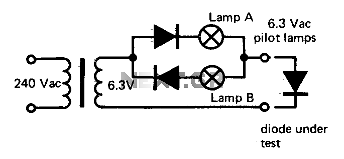
If lamp A or B is illuminated, the diode is functional. If both lamps are illuminated, the diode is short-circuited. If neither lamp lights up, the diode is an open circuit. The described circuit utilizes two indicator lamps, designated as...