
Go no-go diode tester
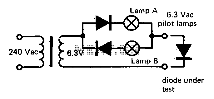
The described circuit utilizes two indicator lamps, designated as lamp A and lamp B, to provide a visual indication of the operational status of a diode within the circuit. The functionality of the diode is assessed based on the state of these lamps.
When lamp A or lamp B is illuminated, it indicates that the diode is in a serviceable condition, allowing current to flow as intended. This situation suggests that the diode is not faulty and is effectively conducting current in the forward direction.
Conversely, if both lamps are illuminated simultaneously, this indicates a short circuit condition across the diode. In this scenario, the diode fails to restrict current flow, leading to a situation where both lamps receive power, which is not typical in a properly functioning circuit.
Lastly, if neither lamp A nor lamp B lights up, it signifies that the diode is in an open circuit state. This condition implies that there is no current flowing through the diode, rendering it non-functional. Consequently, this lack of illumination from both lamps serves as a clear indication of a diode failure.
This circuit can be effectively implemented using a simple series arrangement where the diode is placed in line with a power source and the two indicator lamps. Resistors may also be included to limit the current flowing through the lamps, ensuring they operate within safe limits. The arrangement allows for a straightforward diagnostic tool to assess diode integrity in various electronic applications.If lamp A or B is illuminated, the diode is serviceable. If both light, the diode is short circuited If neither light, ndiode is an open circuit. 🔗 External reference
Related Circuits
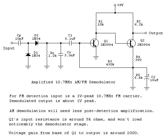
Frequency-to-voltage converters are integral components in various instrumentation circuits and are also utilized in radio applications as FM demodulators. A notable configuration for these applications is the Diode Charge Pump circuit (DCP), which additionally serves as an AM detector....
This small circuit is designed to verify the basic functionality of an infrared remote control unit. The circuit utilizes a straightforward approach by connecting a piezo buzzer directly to an IR receiver integrated circuit (IC). This configuration is as...
Photodiodes convert light into current, and this current can be converted into voltage and amplified. While this process seems straightforward, designing a photodiode detector for gamma photon detection is more complex. Although the circuit is not particularly complicated, the...
This little guide for every electronics tester would actually have to lie in the toolbox. You can have components such as resistors, capacitors, diodes, etc. of testing. T1 and T2 form a Darlington. Therefore only need a small base...
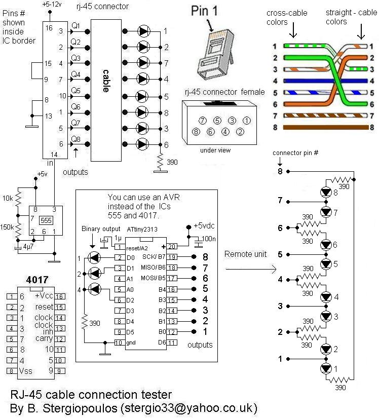
Here is a very simple yet practical circuit designed to check the type of LAN cables (straight or cross) as well as to identify possible faults. The circuit utilizes a unit with 8 outputs, each producing a pulse successively,...
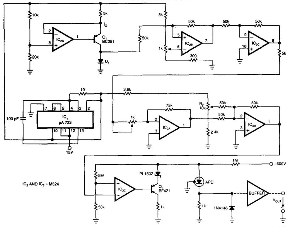
Laser-receiver circuits must bias their avalanche photodiodes (APD) to achieve optimal gain. Unfortunately, an APD's gain depends on the operating temperature. The circuit controls the operating voltage of an APD over a large temperature range to maintain the gain...
Warning: include(partials/cookie-banner.php): Failed to open stream: Permission denied in /var/www/html/nextgr/view-circuit.php on line 713
Warning: include(): Failed opening 'partials/cookie-banner.php' for inclusion (include_path='.:/usr/share/php') in /var/www/html/nextgr/view-circuit.php on line 713