
Automotive electronic locks circuit
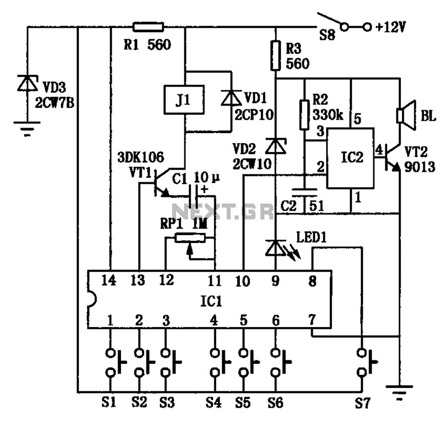
The automotive electronic lock circuit utilizes the 5G058 integrated circuit, which is specifically designed for lock control applications. The circuit operates on a positive voltage supply, which powers the key switches and the lock mechanism. The valid input keys, S1 to S6, are arranged in a sequence that must be followed for the lock to disengage. This sequential input requirement enhances the security of the locking system, as it prevents unauthorized access through random key presses.
The additional key switch, S7, allows for the introduction of false inputs without triggering the lock. This feature can be used for testing or to provide a level of flexibility in key management. The circuit includes a key indicator pin that connects to an LED (LED1). When a valid key is pressed, the LED illuminates, providing visual feedback to the user that the input has been recognized by the system.
In the event of an incorrect key sequence or if the unlocking process exceeds the predetermined time, an alarm output is activated. This serves as a theft deterrent, alerting the vehicle owner or nearby individuals to a potential security breach. The duration of the effective unlocking time is adjustable through the combination of capacitor C1 and potentiometer R1. By varying these components, the circuit designer can tailor the lock's response time to meet specific security needs or user preferences.
Overall, the automotive electronic locks circuit is a sophisticated system that combines security features with user-friendly operation, making it an effective solution for vehicle locking mechanisms. Automotive electronic locks circuit principle is shown in Fig. ICl dedicated lock IC 5G058, it O ~ feet respectively external key switch to the positive power supply, which is six valid input keys, unlock Sl ~ S6 must comply with this order; feet have connected key switch S7 is false key input, you can freely access one or a few keys on the keyboard mixed into real ones; a feet is the key indicator pin during each key communication will make the external light emitting diode emitting LEDl confirm that the key input is valid; ? feet alarm an output terminal, if not by Sl ~ S6 sequentially input or exceed the effective unlocking time, the output high, burglar alarm trigger IC2 language effectively unlocking time by the size of the capacitor C1 and potentiometer RPl to decide.
Related Circuits
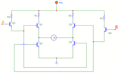
The transistors Q1, Q2, Q3, and Q4 form a bridge circuit. These are typically power transistors designed to handle high current. Transistors Q5 and Q6 drive the bridge. When input A is set high and input B is set...
To charge lead-acid batteries, a circuit can be utilized that consists of a current-limited power supply and a flyback converter topology. The described circuit for charging lead-acid batteries employs a current-limited power supply in conjunction with a flyback converter...
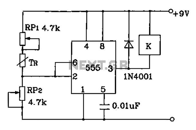
Adjust RP1 and RP2 to set the preset temperature control point. The 555 circuit is configured as a Schmitt inverter circuit that automatically controls a relay device. This forms part of the T-121 temperature control circuit, which includes a...
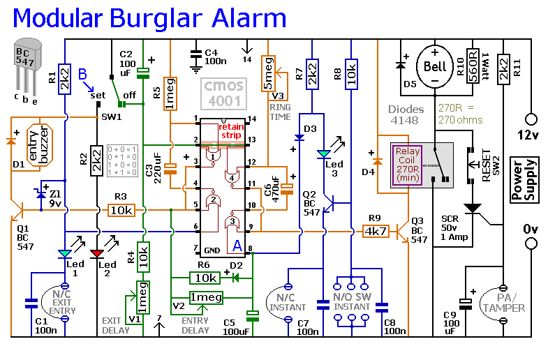
This circuit includes automatic exit and entry delays, as well as a timed bell cut-off feature. It supports both normally-closed and normally-open contacts, and incorporates a 24-hour personal attack/tamper zone. The use of expansion modules allows for the addition...
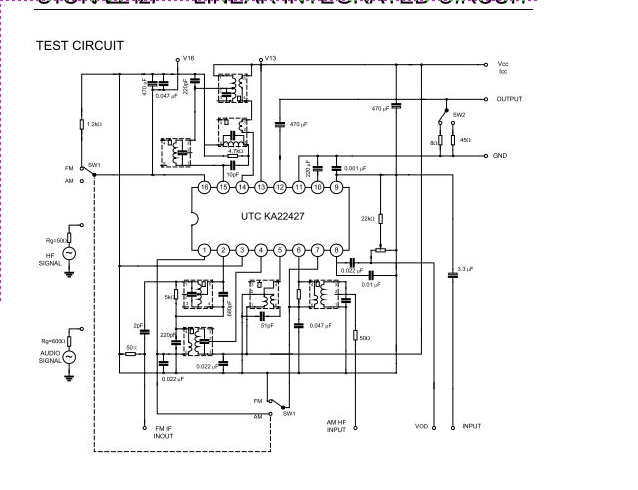
The UTC KA22427 is a single-chip AM/FM radio integrated circuit designed for portable radio applications. It features an AM amplifier, local oscillator, AM mixer, AM/FM amplifier, AM AGC, and FM AGC circuitry. The UTC KA22427 integrated circuit is engineered to...

The simplest example of a Switch Mode Power Supply (SMPS) utilizes three transistors (C3807, A1015, and power transistors). A common issue that arises is related to the feedback circuit, which can lead to an output voltage (B+) that exceeds...