
H-bridge circuit using NPN transistors
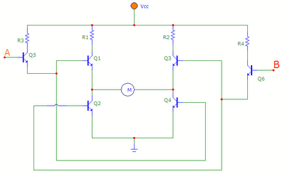
The described circuit utilizes a H-bridge configuration, which is commonly employed in motor control applications. The four transistors (Q1, Q2, Q3, Q4) are arranged in a manner that allows for bidirectional control of the motor. Power transistors are selected for their ability to handle significant current loads, ensuring reliable operation under various conditions.
Transistors Q5 and Q6 act as control switches for the H-bridge. By manipulating the states of inputs A and B, the circuit can effectively control the direction of the motor. When A is high and B is low, Q5 conducts, enabling Q1 and Q4, which completes the circuit path, allowing current to flow through the motor in one direction. This configuration is essential for applications requiring forward motion.
In contrast, when A is low and B is high, Q6 turns on, enabling Q3 and Q2. This configuration reverses the current flow through the motor, allowing it to rotate in the opposite direction. This dual control mechanism provides an efficient means of motor direction control, which is crucial for robotics, automation, and various electromechanical systems.
To ensure safe and efficient operation, it is important to consider the specifications of the transistors, including their voltage and current ratings, as well as the thermal management of the circuit. Proper heat sinks may be required to dissipate heat generated during operation, especially under high load conditions. Additionally, incorporating flyback diodes across the motor terminals can protect the transistors from voltage spikes caused by inductive loads, further enhancing the reliability of the circuit.The transistors Q1, Q2, Q3 and Q4 form the bridge circuit. Generally these are power transistors capable of handling high current. Q5 and Q6 drive the bridge. when the `A` is made high and `B` low, transistor Q5 is on and it makes Q1 and Q4 on. The current flows from vcc to ground through Q1, motor and Q4. hence the motor rotates in forward direction. When `A` is made low and `B` high the transistor Q6 is on and it makes the Q3 and Q2 on. The current flow from vcc to ground through Q3, motor and Q2. hence the motor rotates in reverse direction. 🔗 External reference
Related Circuits
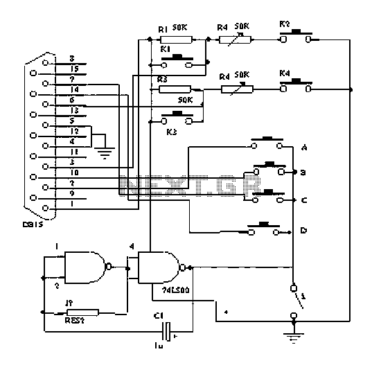
The principle of the dancing blanket is straightforward; it functions as a direct retrofit for a keyboard or gamepad. Each key on the keyboard and gamepad operates as a switch, which connects to the ground through a wire lead....
The following circuit illustrates the Weller WLC100 Electronic Soldering Station Circuit Diagram. This circuit utilizes the Q4012LPH Transistor. Features include safety measures, temperature control, and functionality as a soldering station that performs effectively for various applications. It is a...
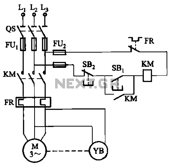
The circuit depicted in Figure 3-121 illustrates the key component of an electromagnetic holding brake, which consists of an electromagnetic brake solenoid primarily made up of two parts: the iron core and the shoe brake components. When power is...
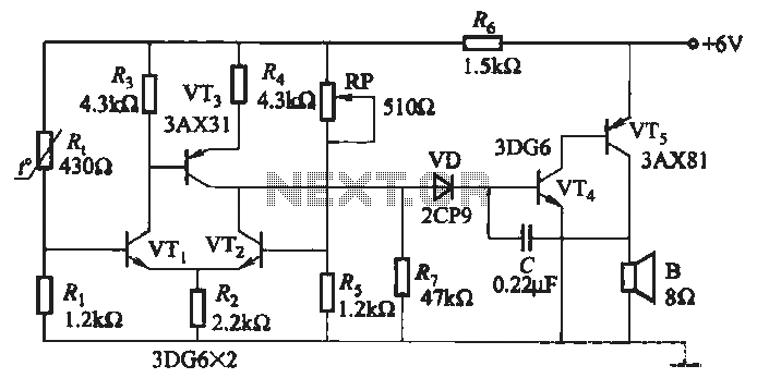
A negative temperature coefficient thermistor is utilized as the temperature sensing element (Rt). The circuit includes a resistor (Ri), a resistor (Rs), a potentiometer (RP), and the thermistor (R) to form a temperature bridge. A differential amplifier is created...

An audio power amplifier circuit for a 3-watt stereo amplifier using the MAX 7910 IC is explained below. The audio power amplifier circuit utilizing the MAX 7910 IC is designed to deliver a maximum output power of 3 watts per...
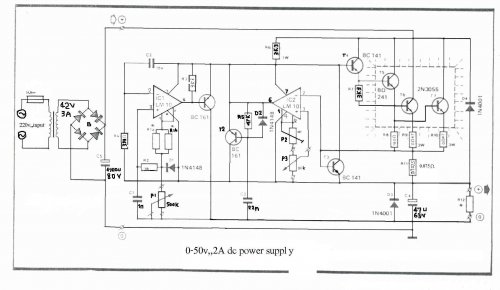
The LM10 integrated circuit (IC) is utilized due to its reference voltage feature, which is advantageous for DC power supply applications. By employing two LM10 ICs, different output voltages and current levels can be achieved. This circuit includes short-circuit...