
KA22427 1 Chip Af/fm Reception Circuit
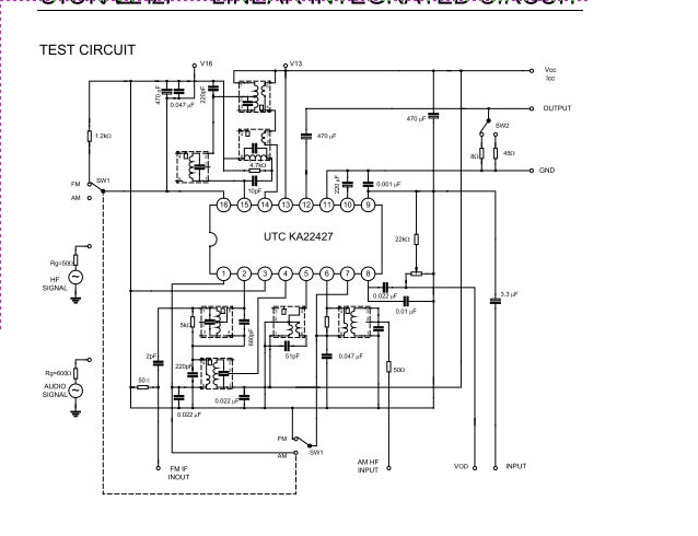
The UTC KA22427 integrated circuit is engineered to facilitate the development of portable AM/FM radios with minimal external components. The design incorporates several key functionalities that enhance performance and usability.
The AM amplifier section boosts weak radio signals to a level suitable for processing, while the local oscillator generates a stable frequency that is essential for the mixing process. The AM mixer combines the incoming signal with the oscillator frequency to produce an intermediate frequency (IF) signal, which is easier to process.
The AM/FM amplifier section provides necessary amplification for both AM and FM signals, ensuring that audio output is clear and of high quality. The Automatic Gain Control (AGC) circuits for both AM and FM help maintain consistent audio levels despite variations in signal strength, thereby improving the listening experience.
This integrated circuit is particularly advantageous for battery-operated devices due to its low power consumption and compact size. The integration of multiple functions into a single chip reduces the overall footprint of the radio circuit, making it suitable for portable applications where space is limited.
The UTC KA22427 is an ideal choice for designers seeking an efficient solution for AM/FM radio functionality in consumer electronics, providing a balance of performance and compact design.UTC KA22427 is a one-chip AM/FM radio integrated circuit that is suitable for portable radio applications. It includes AM amplifier, local OSC, AM mixer, AM/FM amplifier, AM AGE, FM AGE circuit an.. 🔗 External reference
Related Circuits
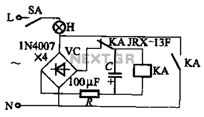
The circuit illustrated in Figure 13-3 consists of two configurations: (a) a DC power supply and (b) an AC power supply. Both configurations are utilized to control a relay. The flash frequency of the relay is determined by the...
The remote control circuit comprises two main components: a transmitter and a receiver. The transmitter circuit is controlled by an NE555 integrated circuit (IC), while the receiver operates based on the frequency of the signal emitted by the transmitter....
A current transformer H11-3 needs to be constructed. Select a transformer core with a minimum power rating of 2W for the first secondary winding. Use enameled wire with a diameter of 0.12 mm and wind approximately 1000 turns. The...
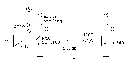
To control a stepper motor, each winding must be energized individually in a specific and timed sequence. This energization is carried out by a driver circuit, which acts as an amplifier. The timing is managed by an indexer circuit,...
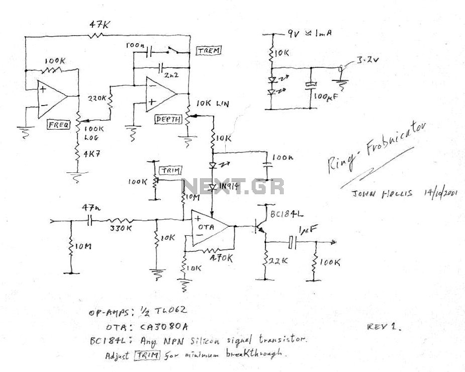
The circuit of the unit is relatively straightforward; however, setting it up can be somewhat challenging. The difficulty arises from the need for matched FETs, which are not easily obtainable. Therefore, it was essential to ensure that the circuit...
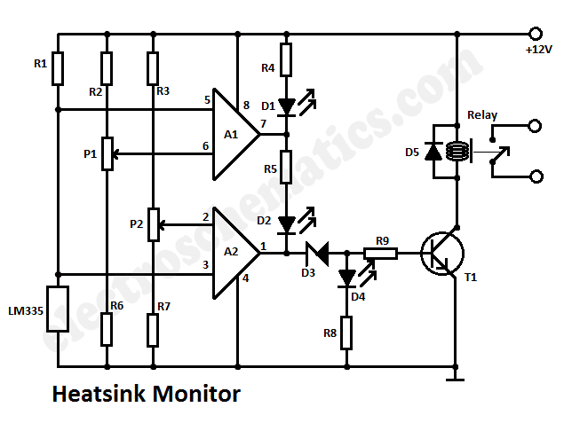
This heatsink temperature monitor circuit uses three LEDs to signal when the temperature exceeds two boundary levels. When the heatsink temperature is below 50 degrees... This heatsink temperature monitor circuit is designed to provide visual indications of temperature levels using...