
Automotive LED Timing Light
The described timing strobe circuit is an effective solution for visual indication of ignition system activity, utilizing high-brightness LEDs to produce a clear and visible strobe effect. The circuit is triggered by detecting ignition pulses from the high-tension lead of the number one cylinder, which serves as a reliable source of timing data for the strobe. The homemade inductive pickup plays a crucial role in this process, capturing the high-voltage pulses and converting them into manageable signals for further processing.
Transistors Q1 and Q2 are configured as buffer and amplifier stages, ensuring that the signals from the inductive pickup are strong enough to drive the subsequent logic stages. The use of Schmitt-trigger inverters provides additional benefits, including noise immunity and the ability to produce clean, well-defined output signals in response to the input pulses. The configuration of three inverters (IC1a, IC1c, and IC1f) allows for robust signal processing, while the subsequent bank of inverters (IC1b, IC1d, and IC1e) ensures that the LED array is activated correctly.
The timing of the LED illumination is controlled by the 6.8nF capacitor, which discharges rapidly upon receiving a pulse, thereby creating a momentary low signal for the second bank of inverters. This design allows for a delayed response, effectively stretching the pulse duration to ensure that the LEDs remain illuminated for a sufficient period, enhancing visibility.
The inductive pickup can be constructed using readily available materials, such as a ferrite core, and requires careful experimentation to optimize the number of turns of wire for reliable signal capture. The use of a cleat to secure the pickup around the high-tension lead ensures stability and consistent performance. Connecting the pickup to the main circuit using shielded microphone cable minimizes the risk of electromagnetic interference, which is critical in automotive environments where numerous sources of noise may be present.
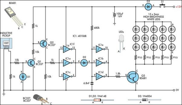
Overall, this timing strobe circuit is a practical and efficient design, suitable for a variety of applications where visual feedback is needed in conjunction with ignition system activity.A useful timing strobe can be constructed using high-brightness LEDs and a few common components. Ignition pulses from the number 1 cylinder high-tension lead are used to trigger the circuit via a home-made inductive pickup. Transistors Q1 & Q2 buffer and amplify the pulses from the pickup, which then drive the inputs of three Schmitt-trigger inve
rters (IC1a, IC1c & IC1f). Each positive pulse at the inverter inputs causes a low pulse at their outputs, forward-biasing D2 and immediately discharging the 6. 8nF capacitor. When the capacitor is discharged, the inputs of the second bank of three inverters (IC1b, IC1d & IC1e) see a logic low level, so their outputs go high, driving Q3 into conduction and powering the LED array.
After the pulse ends, the IC1a, IC1c & IC1f inverter outputs return high, reverse biasing D2. However, it takes some time for the 6. 8nF capacitor to charge to the logic high threshold voltage of the inverters` inputs, effectively stretching the initial pulse width and lighting the LEDs for the required amount of time. The pickup can be salvaged from an old Xenon timing light or made up from a "C" type ferrite or powered iron core large enough to fit around a HT lead.
Some experimentation will be required to determine the number of turns required to achieve reliable triggering. About 100 turns of light-gauge wire proved sufficient on the prototype. A cleat is used to close the magnetic path around the lead and is held in place with a large battery clip.
Miniature screened microphone cable can be used to connect the pickup to the circuit, to prevent interference from other sources. 🔗 External reference
Related Circuits
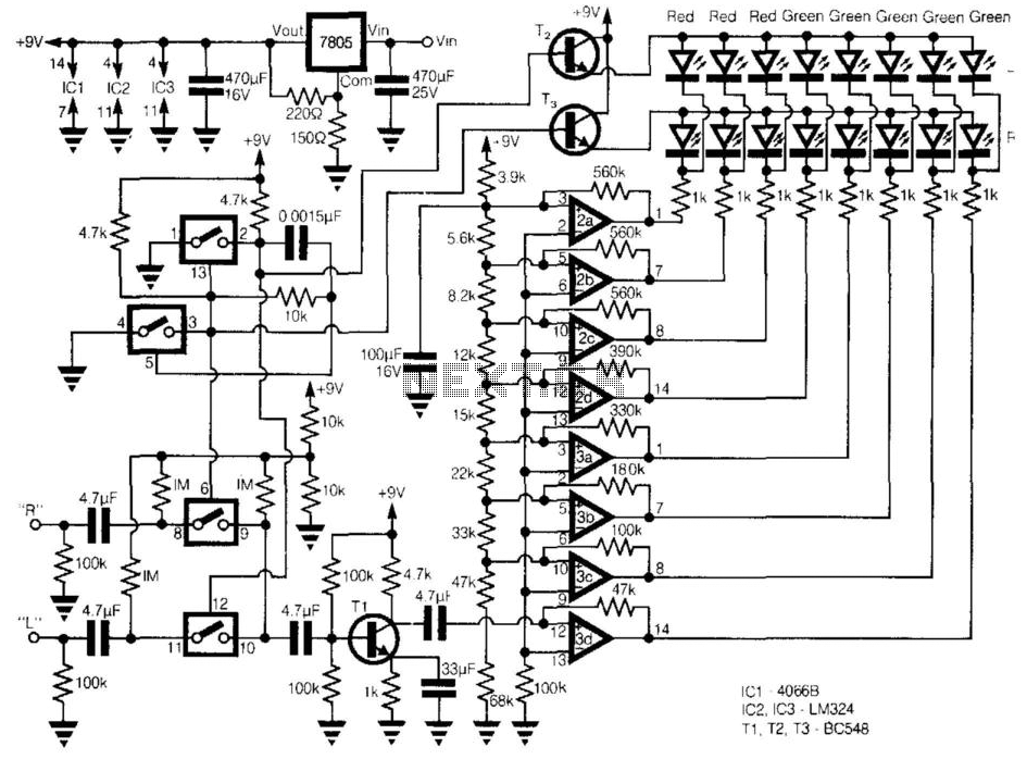
This circuit provides a cheap alternative to the LM3915 series LED displays. The meter relies on a square-wave oscillator built around two CMOS analog switches, which alternatively selects the right and left channels for monitoring and display. The selected...

When discussing fan control, there are generally two methods: linear control and pulse-width modulation (PWM) control. Linear control is the most commonly used method, which involves reducing the voltage supplied to the fan. For a fan rated at 12...
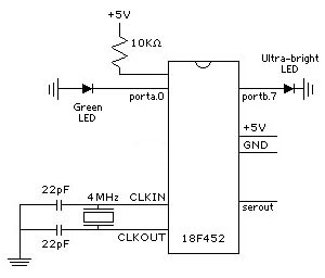
In the project LED Touch Sensing by Jeff Han, a remarkable phenomenon occurs with an LED matrix that not only illuminates but also detects finger touches. Initially, it was assumed that a special type of LED matrix was utilized,...
I like to see lights move to music. This project will indicate the volume level of the audio going to your speakers by lighting up LEDS. The LEDS can be any color so mix them up and really make...
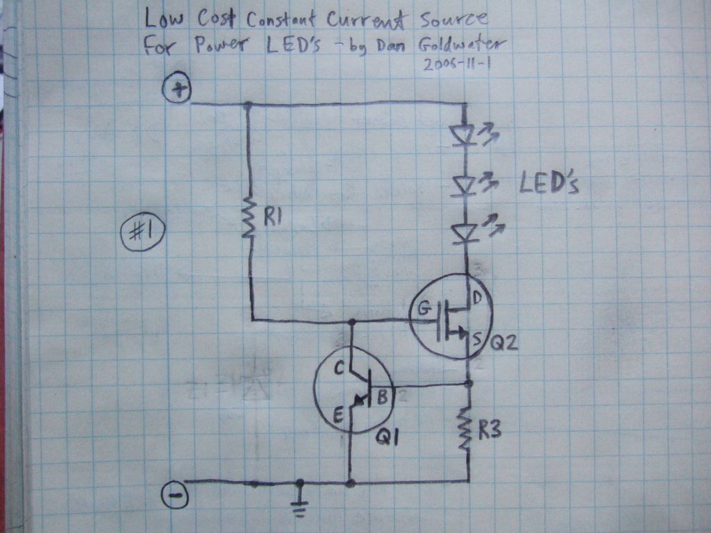
Here is a simple and inexpensive ($1) LED driver circuit. The circuit functions as a constant current source, ensuring that the LED maintains consistent brightness. The LED driver circuit is designed to provide a stable current to the LED, which...
The clock circuit above uses seven ICs and 19 LEDs to indicate binary coded decimal time. The LEDs can be arranged so that each horizontal group of 3 or 4 LEDs represents a decimal digit between 0 and 9...
Warning: include(partials/cookie-banner.php): Failed to open stream: Permission denied in /var/www/html/nextgr/view-circuit.php on line 713
Warning: include(): Failed opening 'partials/cookie-banner.php' for inclusion (include_path='.:/usr/share/php') in /var/www/html/nextgr/view-circuit.php on line 713