
555 car alarm circuit diagram
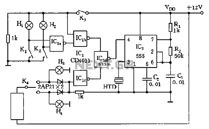
The circuit utilizes a 555 timer in astable mode to generate audible alerts based on specific vehicle conditions. The timer is configured to produce a continuous tone when triggered by low oil pressure and low brake pressure conditions. This is achieved by connecting sensors that detect these conditions to the input pins of the 555 timer. When either sensor detects a fault, it sends a signal to the timer, causing it to activate the alarm.
The quad 2-input NAND gate is employed to provide logical conditions for the circuit. It ensures that the alarm is only triggered when both conditions (low oil pressure and low brake pressure) are met. The outputs from the sensors are fed into the NAND gates, which process the signals and determine if the alarm should sound. The use of NAND gates allows for flexibility in the circuit design, enabling additional features or conditions to be added in the future.
For the steering alert function, a separate circuit can be integrated that monitors the steering position. When the steering wheel is turned, this circuit activates the 555 timer again, but in a different mode, producing an intermittent beep to remind the driver to deactivate the turn signal. This feature enhances driver awareness and promotes safe driving practices.
Overall, this vehicle alarm circuit is a practical application of the 555 timer and logic gates, providing essential alerts to enhance vehicle safety and driver awareness. As shown is 555 more cars with alarm circuit, mainly consists of a 555 and a quad 2-input NAND gate circuit. At the time of low oil pressure and brake pressure is too low, the police will issue a long beep sound; when the car steering, Intermittent sound to alert the driver to turn off the turn signal.
Related Circuits

Many individuals inquire about TV transmitters. This document provides a useful circuit diagram that enables signal transmission over distances of 75 to 100 meters. The circuit diagram is not original; it was provided by a friend. Contributions of circuit...
This circuit regulates a DC power output and has a wide range of applications. It can be utilized to control the speed of a motor, a pump, a toy train, or the brightness of an LED or lamp. Essentially,...
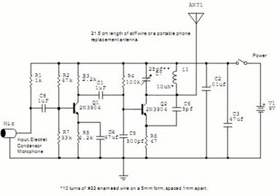
The following circuit illustrates a Wireless Car Alarm Circuit Schematic Diagram. Features include the ability to detect sounds within a 20-meter radius, a 1/16 wavelength antenna, and the capability to transmit radio signals up to 2 kilometers. Q1 serves...
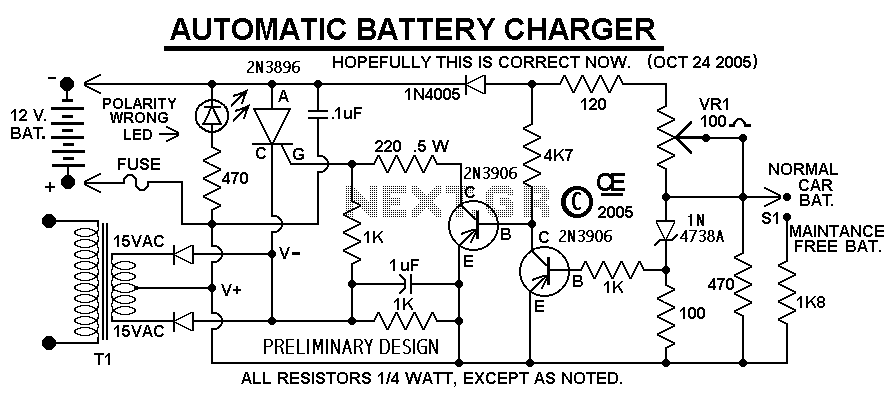
This Charger Can't be used as a Power Supply, Without having a battery in place. The Battery MUST be Connected to get power out. Note: This Charger Features a Reverse polarity Indicator. Instructions: Before plugging this charger into the...
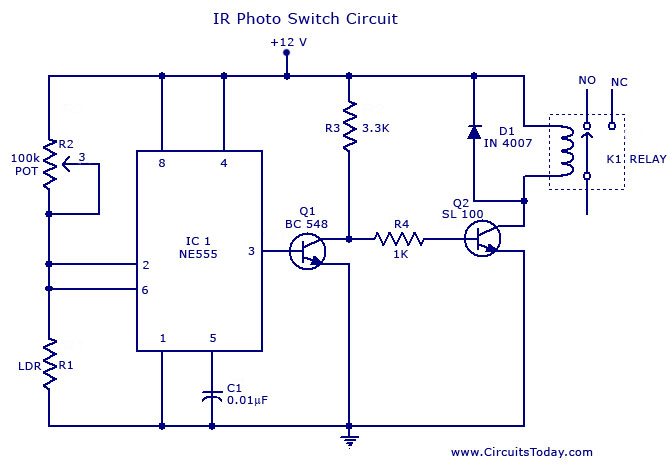
A simple photo switch circuit using an NE 555 IC with a diagram and schematic. This photo switch activates a relay when light intensity crosses a specified limit. It is a light sensor circuit suitable for home and industrial...
This is a simple yet effective darkness activator. It uses a light-dependent resistor (LDR) to detect light, and when no light is present, it activates an alarm from an 8-ohm speaker. The circuit can be easily modified to function...