
Autonomous Parallel Parking RC Car
The RC car is powered by batteries, specifically four AA batteries for the motors, which are housed in the car's battery compartment, and a 9V battery for the PCB. This battery configuration enhances mobility but introduces variability in current supply, complicating velocity calibration as battery charge diminishes. To control the car's movements, the project utilizes an ST Micro L298HN H-Bridge, which allows for bidirectional motor control by switching between positive and negative voltages. The front wheels are controlled by one motor, while the rear wheels are managed by another motor. The control signals for these motors are straightforward, with a +5V signal driving the rear wheels forward and the front wheels left, while a -5V signal reverses the rear wheels and turns the front wheels right.
To prevent inductive spikes from the motors, diodes are incorporated into the H-Bridge output. Three Sharp infrared distance sensors are employed to measure distances to nearby objects, with one placed at the front, one on the right side, and one at the rear. The sensors have varying ranges, with the front and rear sensors covering 4-30 cm and the right side sensor covering 10-80 cm. The sensors' voltage outputs are nonlinear; thus, calibration involves linearizing the output and implementing analog-to-digital conversion (ADC) to ensure reliable distance readings. The ADC function of the microcontroller samples one sensor every millisecond, utilizing the upper eight bits of the ADC output for distance calculations.
The control algorithm consists of state machines that monitor sensor data and determine the required movements. The Forward-Backward (FB) state machine controls the motor for forward and reverse operations, while the Left-Right (LR) state machine governs left and right turns. Each state machine operates within a cycle to ensure precise motor control, allowing for smooth transitions between states based on the flags indicating intended movements. The overall architecture allows for effective multitasking through state machine design, enabling the RC car to navigate and park autonomously.We created an RC Car that can identify a parking space and parallel park by itself. The RC Car drives down a street searching for a parking space to its right using a distance sensor. When the car has identified a space, the car checks to see whether that space is large enough to park in. If it determines that there is sufficient space, the car wi ll begin parallel parking into that space. It uses information from sensors placed on the front, right, and rear of the car to direct the car into the parking space. Once the car has parked, it will remain in that position until it is reset. After discussing various project ideas, we eventually stumbled onto the subject of cars. So we started brainstorming possible projects related driving. When brainstorming, we saw something in the ECE lounge that reminded us of a garage. This led us to parking. Parallel parking is something that many drivers struggle with, yet there are very few tools available to help with parallel parking.
Though a few auto manufacturers have developed systems that can parallel park cars autonomously, these solutions are very expensive. We thought this would be both a fun and interesting problem to tackle using an RC Car as a proxy for a real car.
Our project is broken down into two major components: the control system and the move car algorithm. The move car algorithm directs the car and the control system implements the directions of the move car algorithm. The control system contains all the hardware and its associated software. It allows the parking and parking detection algorithms to interface with the car. The software in this module is broken up into three major sections: the Left-Right/Front-Back (LR/FB) state machines, master state machine, and distance calculations.
The LR/FB state machines determines which direction to move the car based on flags set by the detect parking space and park car algorithms. Once the LR/FB state machines decides which direction to move the car, the master state machine implements this movement by sending the correct input and enable signals to the H-Bridge.
The distance calculations implemented independently every millisecond. Move car contains the detect parking space and parallel parking algorithms. All functions in move car interface with the control module by setting movement flags. The parking space detection and parking algorithms use information from the distance sensors to set these movement flags and guide the car. Move car works by initializing the movement flags of the car. It sets the car on a default trajectory and then calls detect parking space. Once a parking space has been detected, the parking algorithm is called. After the car has successfully parked, it idles until it is reset. When selecting infrared distance sensors there was always a tradeoff between the sensors ability to measure close range and long range.
We tried to minimize this problem by using sensors designed for varying ranges. Using accurate sensors cost significant time. Every measurement from our distance sensors is approximately 40ms delayed. This affected our ability to start and stop the motors of the car at the correct times. We used integer calculations rather than floating point to calculate distances. We decided the increased accuracy would not significantly improve our ability to park the car because we cannot control the movement of the car with that degree of accuracy. We decided to power our car using batteries rather than using a steady power source. This gave us increased mobility but was very inconsistent in the current it supplied to the motors. As the batteries wore out, they supplied less and less current to the motors. This made calibrating the velocity of the car very difficult. In order to best utilize the mobile power resources we have, we power the motors using four AA batteries, which are stored in the battery compartment of the RC car.
These batteries supply the Supply Voltage to the H-bridge, which in turn powers the motor. We use a 9V battery to power the PCB. 1. Our code requires the motor control software, parking algorithm software, and distance sensor software to run in parallel. However, this is not possible in the Atmega644. We got around this issue by making every important task a state machine. By breaking up each function into small pieces, we can execute one piece of function one, then one piece of function two, followed by one piece of function3, and then another piece of function one, etc.
This enables us to emulate a multi-tasking architecture. The first step of our hardware design involved fully understanding the mechanics our RC car. We took apart the car and rebuilt it multiple times to fully understand how it was built, what every part in the car is used for, and how those parts contribute to the control of the car. After understanding the mechanics of the car, we decided the easiest way to control our car would be to directly control the inputs to the DC brush motors controlling the front and rear wheels, bypassing all of the car`s internal circuitry.
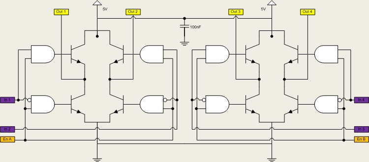
To do this, we scoped the control signals of the car. We found that the control signals were very simple. There is one motor for the reverse and forward movement of the rear wheels and one motor to turn the front wheels left and right. These motors are controlled by a simple 5V DC input. A +5V turns the rear wheels forward and the front wheel to the left. A -5V input turns the rear wheels backwards and turns the front wheels to the right. To more easily control the motors we soldered wires to their plus and minus terminals. This allows us to easily apply a +/-5V without opening up the car again. We use an ST Micro L298HN H-Bridge to control the motors of the RC Car. It allows us to switch between +/-5V across the motor. It also allows us to source the power from the batteries while using the processor to control the transistors in the H-Bridge.
The control algorithm turns the appropriate transistors on/off, applying the proper voltage across the brush motor. The H-Bridge is connected using the following configuration: The first H-Bridge (to the left) is used to control the front motor of the car.
This motor turns the front wheels either left or right. The second H-Bridge (the the right) is used to control the rear motor, which is used for the forward and reverse functionality of the car. The inputs and enables of the H-Bridge are connected to port B. In addition configuring the H-Bridge to control the motors, we also had to protect the H-Bridge from inductive spikes caused by turning the DC brush motors on and off.
We used diodes on the output to protect from these spikes. The H-Bridge was wired as follows: We used three Sharp infrared distance sensors to determine the distance between our car and nearby objects. We placed a sensor on the front, the right side, and the rear of the car. For the front and rear, we used 4-30cm sensors. For the right side, we used we used a 10-80cm sensor. We decided to use a sensor with a larger range for the side so that we could more easily detect a parking space.
However, this made aligning the parking the car more difficult, so we rely more heavily on the front and rear sensors to park the car. To slightly improve the short distance range of our sensors, we placed the sensors as far back on the car as possible.
The challenge with using these sensors is that their voltage output is nonlinear (inverse function) and each sensor varies slightly. Therefore, we scoped the output of each sensor at various distance values, linearized the plot, curve fit the line, and implemented an analog to digital conversion so that we had reliable distance values.
After taking the inverse of the distance versus voltage plots, we determined it would be best to fit the curve using two linear lines rather than one. The equations of the lines are: The analog to digital conversion uses a different equation depending on the value of the measure voltage.
If the measured voltage is above a certain threshold, the ADC will use the equation in the top row. If it is below a certain threshold, the ADC will use the equation in the bottom row. The threshold for the front sensor is 1. 5v and 1. 25v for the rear sensor. When looking at the data for the 10-80cm side sensor plot, we determined that one linear line would be sufficient to accurately capture the output voltage vs. distance characteristics of the sensor. The equation of this line is: For the analog to digital conversion we used the built in ADC function of the MCU.
Because we had three distance sensors, we had to rotate which sensor was connected to the ADC. This was simply done by changing the value of ADMUX. One of the three sensors is sampled every millisecond. We take the value from the ADCH register and perform the appropriate calculation to convert this value to a distance. We decided to use only the ADCH register because the value represented by the bottom two bits of the ADC is on the same order of magnitude as noise.
Therefore, these two bits are not important to our calculation. To do this, the ADC is left adjusted. By using the value in the ADCH register, we are using the upper eight bits of the ten ADC bits. We use the internal reference voltage of 2. 56V for comparison, so our calculation is: The state machines in the AlgorithmModule use the sensor data and various algorithms to determine what should be the next movement the car must make. They assert flags which tell the ControlModule state machines to actually move the motors. The state machines in AlgorithmModule are: The fbStateMachine controls the motor for Forward-Backward operations.
It is controlled by the isForward and isReverse flags. These flags serve as indicators as to whether the car should be traveling forward or reverse. In order to control the velocity of the forward-backward motion we anded the enable bit with a a PWM signal. In State 0, the motor is at rest. The corresponding FB control bits are 00. When the algorithm requires the car to go forward or reverse, the corresponding flags (isForward and isReverse) are set, and the FB state machine switches states to 1 or 3 respectively.
In State 1, the motor rotates to drive the car forward. The state machine remains in this state while isForward is equal to 1. Once isForward is de-asserted, the state machine moves to a buffer state to stop the car from moving forward due to inertia. After isForward is set to 0, leaving state 1 and stopping the motor isn`t enough. The wheels might continue to rotate due to inertia, and so a buffer state, State 2, is required. It makes the motor go in Reverse for 1 cycle (50ms) of the FB State Machine, before going back to the rest state, State 0.
If isReverse is asserted, the state machine jumps to State 3. The state machine remains in this state while isReverse is equal to 1. Once isReverse is de-asserted, the state machine moves to a buffer state to stop the car from moving in reverse due to inertia. After State 3, a buffer state, State 4, is needed to stop the wheels from continuing to rotate in reverse due to inertia.
This is a 1 cycle Forward motion, similar in function to State 2`s reverse functionality. Once done, the FB State Machine goes back to its rest state, State 0. The fbStateMachine is called upon every 50ms. This is enough time to evaluate the flags set in the AlgorithmModule, but at the same time fast enough to make the motor motion very accurate. The lrStateMachine() works the same way are the fbStatemachine. A forward corresponds to a left turn and a right corresponds to a reverse. The diagram for both are: This uses the FB and LR control bits to call the required functions in order to send the appropriate input signals to the H-Bridge and make the motors rotate in the appropriate direction.
As a result, each of the 7 car movements (stop, forward, forward-left, forward-right, reverse, reverse-left, reverse-right) have a unique masterBits combination associated with them. The master control bits are then used in the function to decide which motor control function is to be called.
This state machine is invoked in each iteration of the infinite while loop in main. any 2-wheel drive R/C car. 🔗 External reference
Related Circuits
The circuit is designed to operate with an external power supply, which is why it does not include a transformer, rectifier, or filter capacitors in the schematic. However, these components can be added if desired. To utilize the circuit,...
The Car shows the distance a train travels on a 5 digit LCD display. The distance is indicated down to 1/100th of a mile (about the length of a 50 foot car) with an accuracy of approximately plus 2...
The car parking sensor circuit utilizes a photodiode as the distance sensor. It measures the distance between adjacent sensors. The car parking sensor circuit employs photodiodes to detect the proximity of obstacles, enhancing parking safety and convenience. Photodiodes are semiconductor...
Below is a comparator circuit that can measure the voltage of a car battery in 1-volt steps. The voltage indication is achieved through a comparison mechanism. The described comparator circuit is designed to accurately measure and indicate the voltage level...

This simple circuit drives six LEDs in a "Knightrider scanner mode." Power consumption primarily depends on the type of LEDs used, particularly when utilizing a 7555 (the CMOS version of the 555 timer). The circuit is designed to create a...
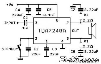
The following circuit diagram is a bridge amplifier specifically designed for car audio systems. The circuit is very simple, utilizing a few external components to support the power IC TDA7240A. This circuit will produce a maximum power output of... The...