
Long range FM transmitter
The long-range FM transmitter operates by modulating a carrier frequency with an audio signal, allowing for the transmission of sound over considerable distances. To enhance the transmission range, the circuit typically includes several key components, such as an oscillator, a modulator, and an antenna.
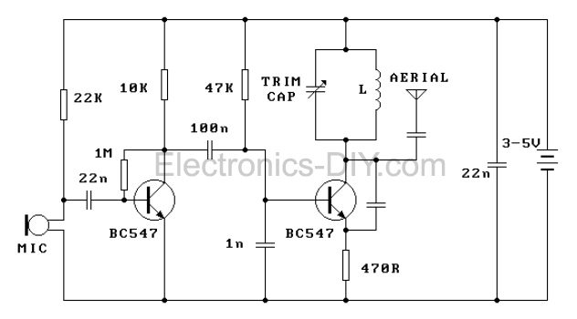
The oscillator generates a stable frequency, which serves as the carrier wave. This can be achieved using a Colpitts or Hartley oscillator configuration, known for their reliability in producing sine waves. The frequency is usually adjustable to avoid interference with other stations.
The modulator stage combines the audio input with the carrier wave. This is often accomplished using a transistor configured as a mixer, where the audio signal is superimposed onto the carrier frequency, resulting in frequency modulation. The choice of transistor is crucial, as it must handle the desired frequency range and provide sufficient linearity to ensure high-quality audio transmission.
To amplify the output signal, a power amplifier stage can be added, which is often omitted in basic designs. This stage increases the output power to drive the antenna more effectively, thus extending the transmission range. Common configurations include class A or class C amplifiers, with the latter being more efficient for RF applications.
The antenna design also plays a critical role in the performance of the transmitter. A dipole or monopole antenna can be used, depending on the desired range and frequency. The antenna must be tuned to the transmitter's frequency to maximize radiation efficiency.
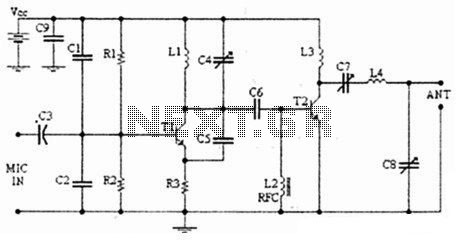
Overall, while many basic FM transmitter circuits may lack amplification stages, incorporating these additional components significantly enhances the transmission range and audio quality, making it suitable for various applications, such as broadcasting or personal use.Long range FM transmitter. The power output of most of these circuits are very low because no power amplifier stages were incorporated. The transmitter circuit described here has an. 🔗 External reference
Related Circuits
A highly effective 1-watt FM transmitter circuit that is easy to construct. The circuit consists of four transistors: one functions as a stable oscillator, followed by a buffer stage to maintain frequency stability during adjustments. Next is a resonance...
This FM transmitter is one of the simplest and most basic designs that can be built while still providing a useful transmitting range. Despite its small component count and 3V operating voltage, it is surprisingly powerful, capable of transmitting...
In 1896, Marconi successfully transmitted electromagnetic waves over a distance of approximately 3 kilometers. Shortly thereafter, he established radio communication across water between Lavernock Point in South Wales and Flat Holm Island. The transmitter utilized a spark inductor connected...
The following diagram illustrates an FM transmitter circuit capable of FM transmission up to 4W. The voltage supply for this circuit ranges from 12V to 16V, with a current consumption between 100mA and 400mA. This circuit operates within an...
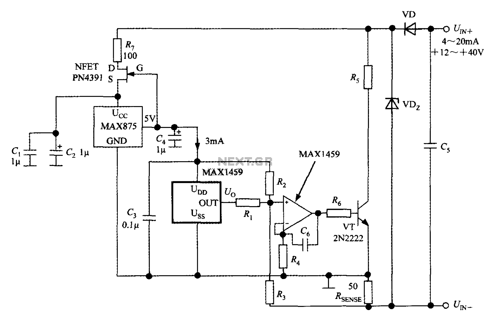
A 4 to 20 mA current transmitter circuit is implemented using the MAX1459, as illustrated in the accompanying figure. The output voltage from the programmable gain amplifier (PGA) is supplied to a spare amplifier chip, and subsequently, an external...
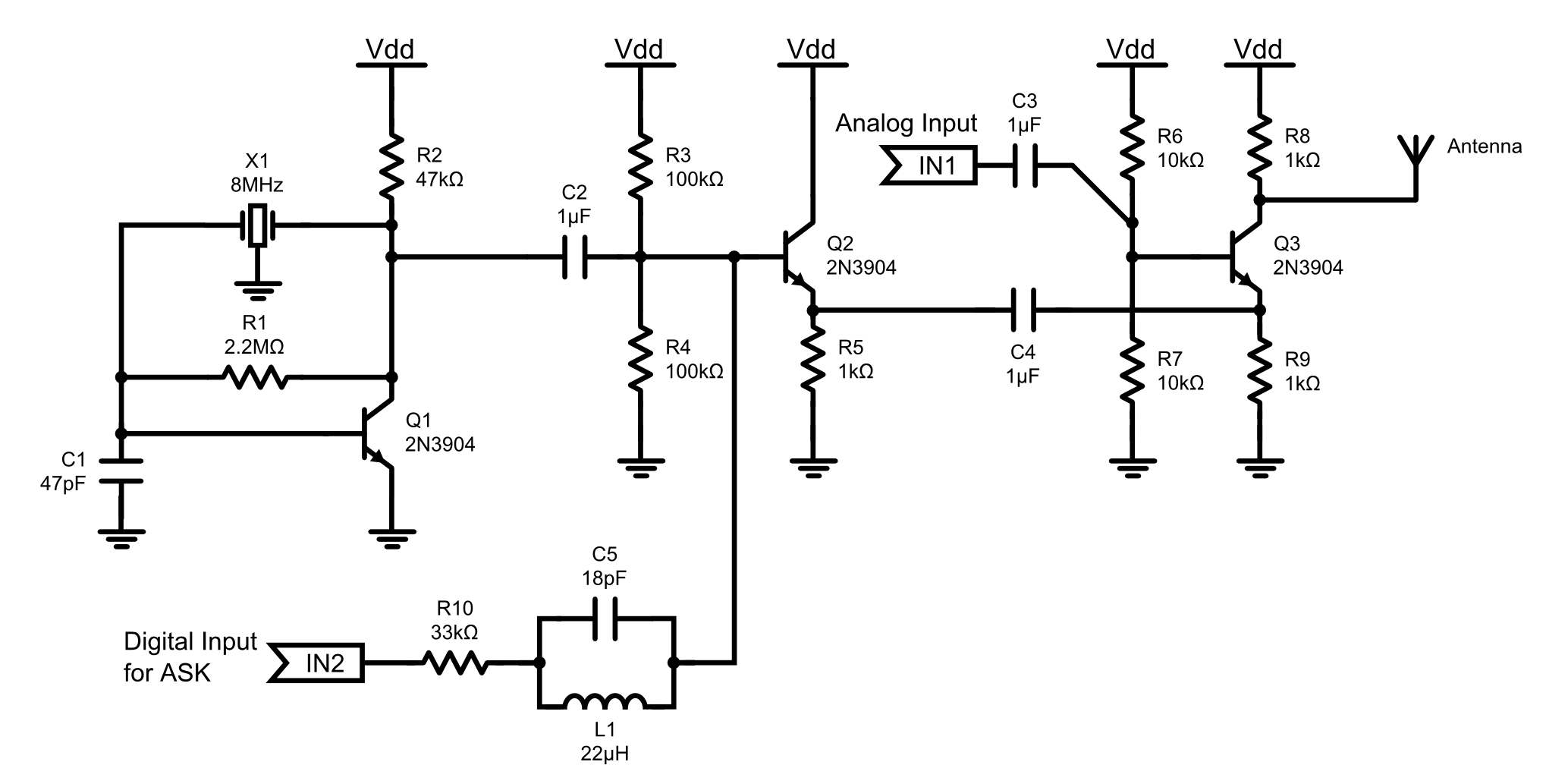
This is an 8MHz amplitude modulated (AM) radio transmitter designed primarily for practical applications and as an educational exercise in electronics. The objective was to create a simple radio transceiver that could be used in future projects requiring basic...