
Available units selected from 10 to 10dB 90dB programmable gain amplifier
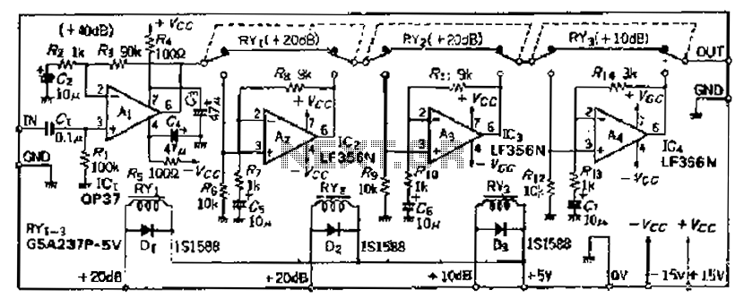
The described amplifier circuit utilizes an OP37 operational amplifier as the primary input stage, which is known for its low noise and high precision, making it suitable for applications requiring high gain without significant distortion. The circuit design incorporates a series resistance configuration to optimize the gain setting, ensuring that the desired amplification level is achieved without introducing excessive noise or distortion.
In this configuration, the absence of a 9kΩ resistor suggests a tailored approach to impedance matching and gain selection, which may be crucial for specific signal processing requirements. The use of additional filtering components, such as resistors g5 and chu 5 along with capacitor c4, indicates a proactive measure to mitigate power supply noise, which can adversely affect the performance of sensitive amplifier circuits. This filtering stage is essential in maintaining signal integrity, particularly in environments where electromagnetic interference (EMI) is prevalent.
The circuit's design allows for the use of standard operational amplifiers for stages Ai and As, provided that they meet the necessary specifications, particularly in terms of slew rate. A minimum conversion rate of 10 V/s is mandated to ensure that the amplifier can respond adequately to rapid changes in input signals without introducing lag or distortion.
To further enhance performance, the inclusion of a 1011F capacitor in the amplifier stage is a strategic choice aimed at stabilizing the DC offset voltage. This component helps to maintain the desired operating point of the amplifier, ensuring that the gain remains consistent at a factor of 10. This careful balance of components and design principles is fundamental in achieving a high-performance amplifier circuit that meets the requirements of modern electronic applications.Although the basic amplifier circuit phase AC amplifier are the same, no special change, but in order to select the correct magnification, the circuit uses ugly series resistan ce does not have 9k0. Resistance. The input amplifier Ai selected OP37 (even if magnification is large, deterioration of properties is small, does not fill phase compensation) in order to remove the power supply line broadband noise, the circuit increased by the clamor, g5 and chu 5, c4 filter constituted. Although Ai ~ As can adopt a common OP amplifier, but the conversion rate should be 10 V/s or more. In order not to increase the DC offset voltage amplifier stage equipment are used 1011F electric vessel so that the flow at a magnification of 10 wins
Related Circuits
The problem with class-B amplifier design is that we start with an output stage in two halves, each with a non-linear response, which we then add together to try to give a linear response, i.e. so that a graph...
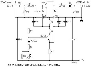
The circuit is designed for driving small UHF TV transmitters, providing a gain of 7 dB and capable of amplifying signals within the frequency range of 470-860 MHz. Key components include resistors, capacitors, and transistors. This circuit serves as a...
A careful examination of the amplifier photos reveals that the heatsink on the HY60 near-clone built using the TDA2050A is slightly shorter than that of the original HY60s. This unit is positioned at the rear of the amplifier, creating...
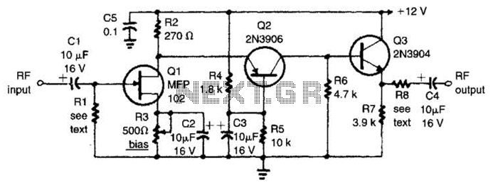
The circuit features a frequency response that spans from 100 Hz to 3 MHz, with a gain of approximately 30 dB. Field-effect transistor Q1 is arranged in a common-source self-biased configuration, and an optional resistor R1 is available to...
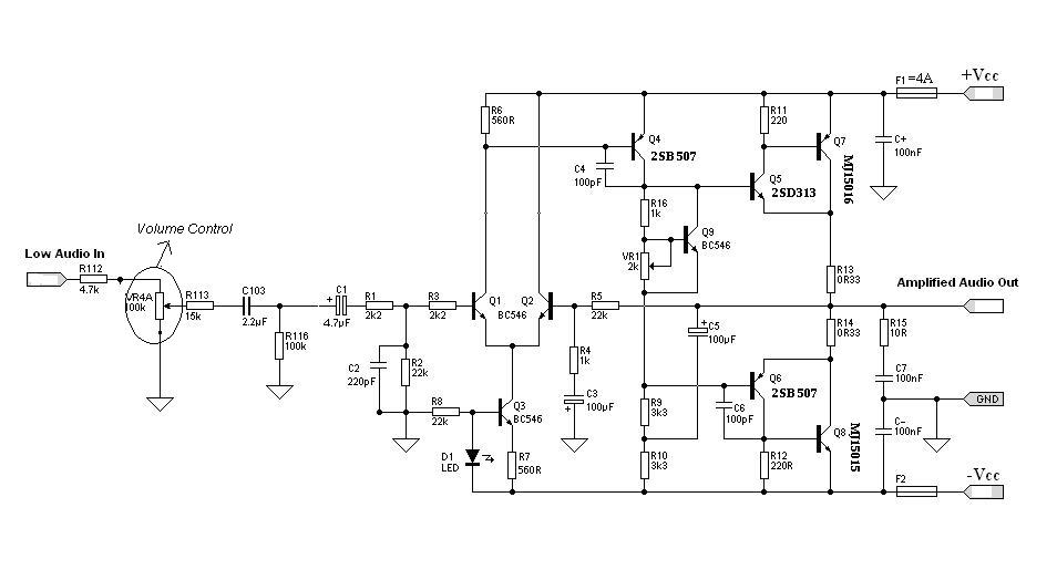
Designing an audio amplifier from scratch using discrete components is an engaging task, as it enables users to create amplifiers that meet diverse requirements. Audio amplifiers can enhance low-level sounds from mobile devices, making them louder and more vibrant....

The E1T tube has been a part of the family for many years. It was likely brought home by my father, who worked at the Shell laboratory in Rotterdam, or purchased from surplus shops we visited on Saturday mornings...
Warning: include(partials/cookie-banner.php): Failed to open stream: Permission denied in /var/www/html/nextgr/view-circuit.php on line 713
Warning: include(): Failed opening 'partials/cookie-banner.php' for inclusion (include_path='.:/usr/share/php') in /var/www/html/nextgr/view-circuit.php on line 713