
AVR Atmega32 flash verification error
The Atmega32A microcontroller is part of Atmel’s AVR family and is widely used in various applications due to its versatility and performance. The microcontroller features a 32KB flash memory, 2KB SRAM, and 1KB EEPROM, making it suitable for a range of projects. The USBasp programmer is a popular tool for programming AVR microcontrollers, providing a convenient interface for uploading code and configuring fuses.
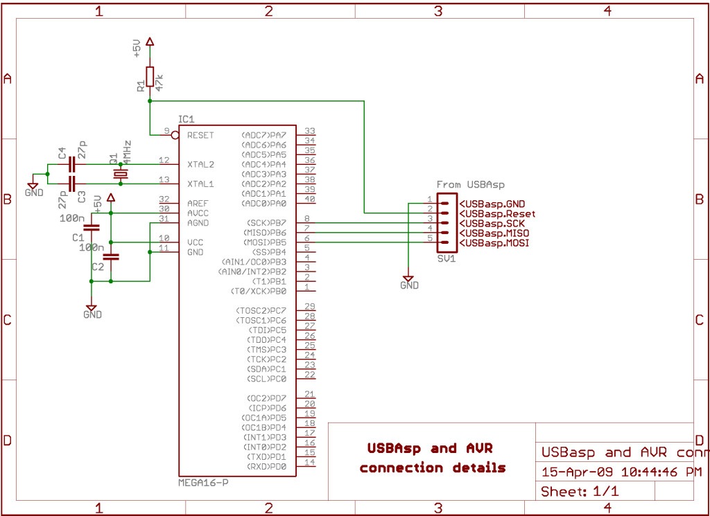
In this scenario, the programming process involves using the SPI (Serial Peripheral Interface) protocol, which requires precise timing and the correct sequence of signals. The programming connection typically includes the following lines: MOSI (Master Out Slave In), MISO (Master In Slave Out), SCK (Serial Clock), RESET, and VCC/GND. Proper connection and configuration of these lines are crucial for successful communication between the programmer and the microcontroller.
To verify that the device is responding correctly, the programmer should first check that the fuse bits have been altered as intended. This can be done by reading back the fuse settings after programming. If the expected values are not returned, it may indicate a communication issue or a malfunctioning chip. The echoing of the second byte ($53) during the Programming Enable sequence serves as a critical check; if the echo does not occur, it suggests that the communication is not synchronized, necessitating troubleshooting steps such as resetting the device.
When designing a programmer or troubleshooting an existing setup, it is essential to ensure that all connections are secure and that the programmer settings match the requirements of the Atmega32A. Utilizing an oscilloscope to monitor the signals on the MISO line can provide insights into the communication status and help identify any potential issues. If problems persist despite following these guidelines, testing with alternate chips from the same family may help determine if the original chip is defective or if the programmer is at fault.An Atmega32A chip and I`ve been trying to program it with a usbasp for quite a few hours. I can change the fuses and write the program, but verification fails. The chip can be erased and fuses can be changed, my only problem is with the verification. The program seems to be written to memory but my LEDs aren`t blinking. I would like tosee two things. Confirmation of a working programmer for this chip and an explanation of how you know it is connected properly and how to go about designing one. This will be getting a bounty when it hits the age that I may add one. Kortuk™ Jul 26 `11 at 14:50 How many times have you written to/from the chip There are a limited number of writes, and it`s also possible that you have a defective one (if you`re sure all of your programmer settings are correct and there is no bad connection). Breakthrough Jul 29 `11 at 14:16 How do you hook up a flash programmer for this chip and what are the lines for!
300 rep here, Begging for someone to answer now. Kortuk™ Aug 1 `11 at 4:44 Have you been able to verify at all that the device is responding at any level You say you programmed the fuse bits, but have you been able to verify that they were actually changed The SPI Serial Programming instructions will not work if the communication is out of synchronization. When in sync. the second byte ($53), will echo back when issuing the third byte of the Programming Enable instruction.
Whether the echo is correct or not, all four bytes of the instruction must be transmitted. If the $53 did not echo back, give RESET a positive pulse and issue a new Programming Enable command. Perhaps you could see if you can test this, either with an option to/modification of avrdude, or even just looking with a scope to see if the miso line is wiggling at all I`d think the question has aged enough that if it`s still an issue, ordering any older chips from the atmega8/16/32 family to test the programmer would be worthwhile.
The atmel literature seems to imply that the change are primarily fab process related, so it`s possible that the new device might be more noise sensitive in some respects. 🔗 External reference
Related Circuits
The basic two-transistor flasher has become widely utilized in various applications due to its simplicity and versatility. It has been employed in circuits such as a micropower low battery indicator, a lightning detector, an off-line switching power supply, a...
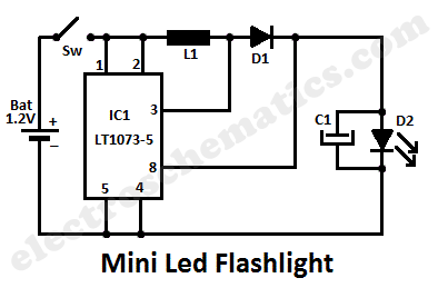
This LED lamp circuit can be utilized as a mini LED flashlight. When paired with a 1.2 V rechargeable battery, all components can be housed within a compact enclosure. The mini LED flashlight circuit typically consists of several key components:...
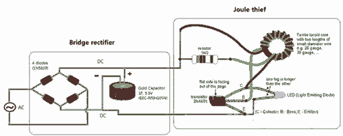
Breathe down and come out on the bright flashlight. In order to promote the voltage, pieces of a highly skilled Joule thief circuit have been used. The Joule thief circuit is a minimalist, low-power boost converter designed to extract energy...
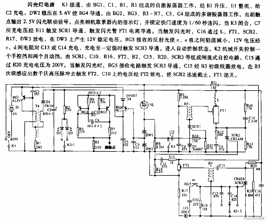
The camera flashlight circuit activates when switch K1 is engaged. This triggers a self-oscillating circuit consisting of BG1, capacitor C1, battery B1, and resistor R1. Once operational, the circuit boosts the voltage through B1 and rectifies it using diode...
Many friends have requested an automatic on/off LED circuit or an LED flashing circuit. This post presents an astable multivibrator circuit designed for LED flashing. It is a simple astable multivibrator circuit utilizing two LEDs (specifically red LEDs) and...
This LED flasher circuit utilizes a 555 integrated circuit (IC) and is designed to drive multiple LEDs. Notably, connecting several LEDs in series does not increase the power consumption. The LED flasher circuit based on the 555 timer IC is...