
AVR ISP programmer In-System Programmer
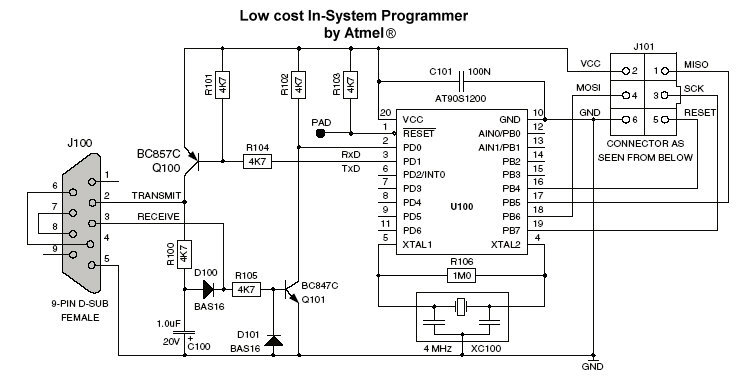
The described programmer circuit is designed for use with AVR microcontrollers, specifically targeting devices like the AT90S2313, AT90S2343, and ATmega161. The circuit requires the integration of a 4 MHz crystal oscillator, which is essential for timing operations in microcontroller applications. The crystal should be connected to the XTAL1 and XTAL2 pins of the microcontroller to ensure stable clock generation.
In cases where microcontrollers with internal oscillators are used, such as the AT90S2343 or ATmega161, the external crystal is unnecessary, provided that the internal oscillator is enabled. This feature simplifies the design and reduces component count, thereby enhancing reliability.
For communication between the master microcontroller (AT90S1200) and a PC, the circuit can incorporate either the MAX232 or MAX202 integrated circuits. These components serve as level shifters to convert TTL logic levels to RS-232 levels, facilitating serial communication. The use of these ICs can replace discrete components like transistors, capacitors, and resistors, streamlining the design process and improving performance. The MAX202, in particular, has been tested successfully in this configuration, ensuring robust communication with the PC.
Overall, this programmer circuit exemplifies a well-thought-out design that balances functionality with simplicity, making it an excellent choice for programming AVR microcontrollers.Programmer in my "AVR software and technical Library - April 2003" CD-rom and decide to publish it. The reason was, that this programmer is very stable and works perfect with AVR Studio 4. I hadtested it before published it, with AT90s2313 and its worked fine! To work this programmer you must to connect acrystal 4MHz to slave device at theXTAL1 and XTAL2pins, or if you have an device with internal oscillator (AT90S2343, ATmega161 etc) and its enabled, its not need any external oscillator. If you want you canuse MAX232 or MAX202 instead transistors, capacitors and resistors to connect master AT90S1200 with Personal Computer (PC).
There is no problem (i check this hardware by using MAX202). 🔗 External reference
Related Circuits

This project originated from the need to control home heating remotely from work. Utilizing a VPN connection between work and home, a relay controlled by a PC was considered the simplest solution. However, a control unit that could be...
Many applications require a large number of keys connected to a computing system. Examples include PC keyboards, cell phone keypads, and calculators. Connecting a single key to a microcontroller unit (MCU) is straightforward; however, connecting 10 or 100 keys...
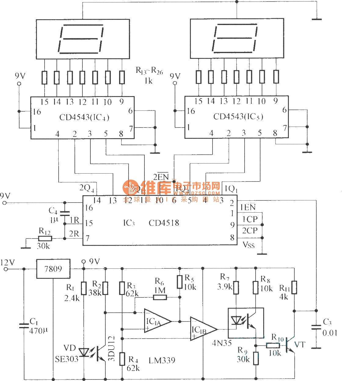
The circuit includes an optical input circuit (VD, 3DU12), a pulse forming circuit (IC1A, IC1B functioning as a voltage comparator; optical coupler; transistor switching circuit), and a counting and display circuit. The circuit architecture consists of several key components that...
Microcontrollers (MCUs) are versatile integrated circuits (ICs) that enhance the functionality of electronics, robotics, and various other projects. Microcontrollers serve as the brain of embedded systems, providing control, processing, and communication capabilities in a compact form factor. They typically consist...
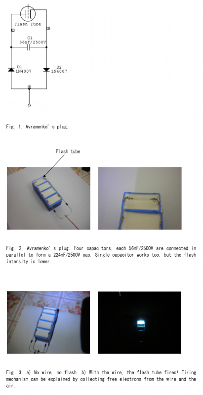
Avramenko is a Russian scientist who invented a plug designed to transmit electrical energy over a single wire. This simple circuit comprises two diodes, one capacitor, and a flash tube. The high-voltage (HV) terminal connects to the HV output...
Its an adaptation of the 2X 16 LCD project, by adding a ferrite loop antenna, two resistors, and a capacitor. Here the display shows the output of the 10 bit scanning voltmeter with Minimum Mass Wireless Coupler. Both the...