
LED based transistor tester
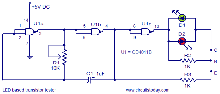
The transistor tester circuit operates by generating a square wave signal that is fed to the transistor under test. The square wave oscillator formed by gates U1a and U1b, R1, and C1 produces a periodic signal whose frequency is adjustable, allowing for flexibility depending on the testing requirements. The output from this oscillator is split into two paths: one path through gate U1c inverts the signal before it reaches the base of the transistor, while the other path directly connects to the emitter.
Resistor R2 is crucial as it limits the base current to the transistor, ensuring that the transistor operates within its safe limits. Similarly, resistor R3 serves to limit the current flowing into the emitter, protecting both the transistor and the circuit components. The use of two LEDs provides a straightforward visual indication of the transistor's condition. The red LED is configured to light up when a good NPN transistor is present, while the green LED lights up for a good PNP transistor, allowing for quick identification of the transistor type and its operational status.
In cases where both LEDs are illuminated, it indicates a short circuit condition, which may occur due to internal damage within the transistor. Conversely, if neither LED lights up, this could signify a defective transistor or incorrect wiring, prompting a review of the connections. The simplicity of this circuit, coupled with its effectiveness in testing both types of bipolar junction transistors, makes it an invaluable tool for electronics enthusiasts and professionals alike.Here is the circuit of a very simple transistor tester which used two LEDs for displaying the condition of a transistor. Both PNP as well as NPN transistors can be tested using this circuit. Quad 2 input CMOS NAND gate IC CD4011B is the heart of the circuit. Out of the four NAND gates inside the IC, only three are used here and they are used as NO T gates by shorting their input terminals. Gates U1a, U1b, resistor R1 and capacitor C1 forms a square wave oscillator. The frequency of this oscillator can be adjusted by using R1. The output of the oscillator is inverted using the gate U1c. The inverted oscillator output is connected to the base of the transistor under test through the resistor R2 and the non inverted oscillator output is connected to the emitter of the transistor under test using the resistor R3. The status of the LEDs D1 and D2 reveals the condition of the transistor under test. If red LED is ON, It indicates that the transistor under test is a good NPN. If green LED is ON, it indicates that the transistor under test is a good PNP. If both LEDs are ON, it indicates that the transistor under test is short. If both LEDs are OFF, it indicates that either the transistor is bad or you may have connected it incorrectly.
🔗 External reference
Related Circuits

This analog switch utilizes the 2N4860 JFET, which features a low on-resistance of 25 ohms and minimal leakage current. The LM102 is employed as a voltage buffer in the circuit. Additionally, this configuration can be modified for use in...

A basic LED driver circuit consists of a 5-volt power source, a 2 kΩ potentiometer, and an LED. The LED is forward biased, with the manufacturer specifying a maximum current rating of 20 mA at a diode voltage drop...
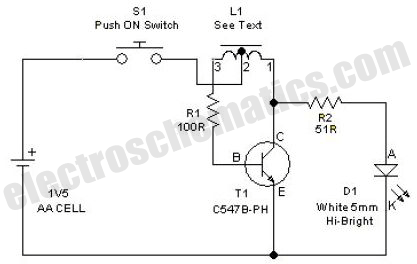
This simple LED driver circuit allows the operation of up to seven LEDs using a single NiMH (Nickel Metal Hydride) AA cell. The circuit generates voltage pulses. The LED driver circuit is designed to efficiently power multiple LEDs while maintaining...

For applications requiring a large number of LEDs, traditional methods can become inefficient, prompting the need to minimize the voltage drop across the resistor. This approach can lead to inadequate current control. Integrated circuits (ICs) like the MM5450 and...
This is a simple LED flasher using two 2N3904 transistors. Classic astable multivibrator using 2 transistors. Transistor is not critical. Try these: 2N4401, 2N2222, NTE123A, NTE123AP, NTE159, TUP/TUN and those in your junk box, you may find that most...

Here is the new flasher circuit schematic. It consists of a 555 timer circuit and a power transistor. The power transistor is likely over-specified, as it is rated at 10A, but it is the component that was available. The...