
avr programmer
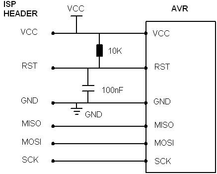
This circuit diagram represents an efficient and straightforward implementation of an AVR microcontroller programmer, suitable for hobbyists and engineers alike. The use of a general-purpose matrix PCB simplifies the assembly process, allowing for easy modifications and repairs. The choice of PonyProg2000 software facilitates user-friendly programming of the AVR microcontroller, which is essential for developing various applications.
The interconnection of the MISO, MOSI, SCK, RESET, X1, X2, VCC, and GND pins ensures that the programmer can effectively communicate with the microcontroller. The serial port connection is a significant advantage, as it allows for longer cable lengths without signal degradation, making it ideal for setups requiring distance between the programmer and the microcontroller.
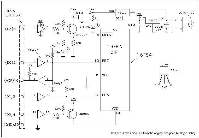
The inclusion of diodes and a zener diode for voltage clamping is a critical safety feature. The clamping of +12V to +5.0V and -12V to -0.3V protects the microcontroller from overvoltage conditions, which could otherwise lead to damage or malfunction. The choice of diodes is also important; while alternatives like the 1N4148 may be available, using the BAT85 ensures that the voltage levels remain within the safe operating range specified in the microcontroller's datasheet.
The programming process is straightforward, with clear steps to configure the software settings. Selecting the appropriate serial port and adjusting the reset inversion ensures that the programming process proceeds smoothly. This attention to detail enhances the reliability of the programmer and the overall success of the microcontroller programming task.Following circuit diagram shows ultra simple AVR microcontroller (SOURCE: unkown). It requires very few components and its very simple to build on general purpose matrix PCB. You can use PonyProg2000 software to program your AVR using this programmer. Following photograph shows programmer I have made for 40Pin and 20Pin AVR µCs. MISO, MOSI, SCK, RESET, X1, X2, VCC and GND pins of both 40pin and 20pin sockets are connected together. Serial port programmer(reference: At-Prog ) is shown here. Main advantage of using serial port is you can have cable length upto 2m. You can use PonyProg2000 software to program your AVR using this programmer. Serial port generates +- 12V on its pins, thus diodes and zener diode is used to clamp +12V to +5. 0V(4. 7V due to zener + 0. 3V due to bat85) and -12V to -0. 3V (due to lower Bat85). You can substitute Bat85 with 1n4148, however it is not recommended because, this diode will clamp +12V and -12V to +5. 4V and -0. 7V which are not desirable, as per datasheet of microcontroller. Its not that micro will burn if you use 1N4148 diodes, but why to take risk !. All steps are same as described in parallel port programmer section, However during third step do the following settings : select serial , from list select SI prog I/O , select COM1 ³( usually serial port is at COM1, if your computer have more than one serial ports multiple options will be active.
Select appropriate, if you know, else do trial&error), check Invert Reset . Click on OK. 🔗 External reference
Related Circuits
A universal Windows-based software designed to work with any serial programmers for the PIC16F84, known as WPicProg16 V1.20. It is recommended to build this programmer before starting various interesting projects with the F84. Some PIC programmers support in-circuit programming,...
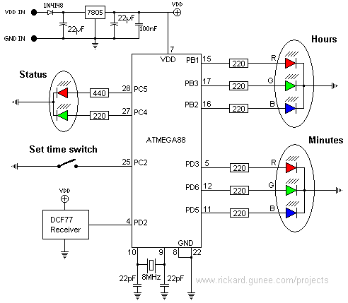
This page describes a color clock that displays the time using two RGB LEDs, one for hours and one for minutes. It uses standard color coding for components, with two additional colors to accommodate the twelve distinct color representations...
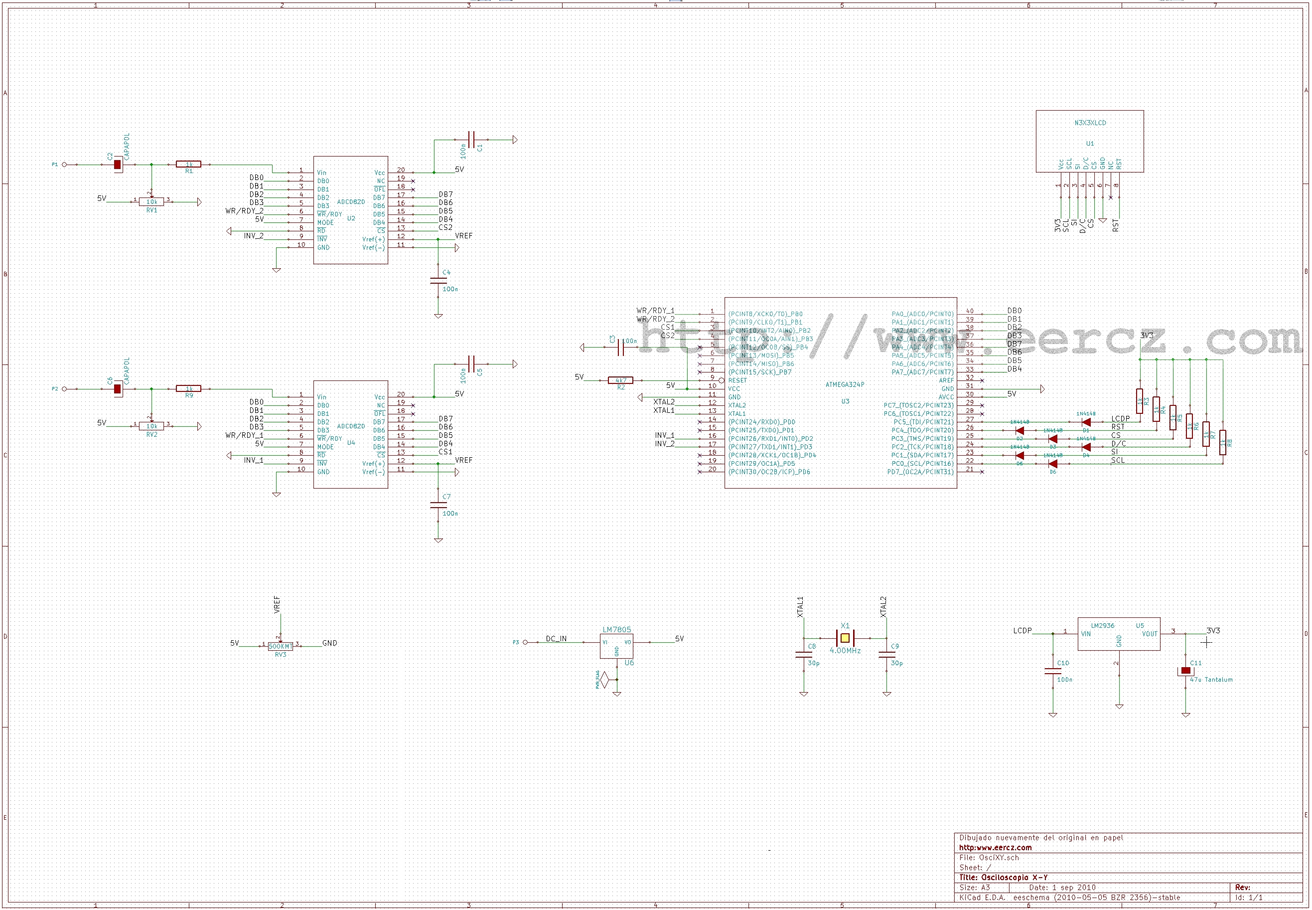
This is a straightforward X-Y oscilloscope design utilizing an ATmega324P microcontroller and two KAD0820 analog-to-digital converters (similar to National Semiconductor's ADC0820). The initial version of this oscilloscope was based on an AT90S4414, necessitating the use of external ADCs. Various...

This ISP programmer can be utilized for both in-system programming and as a standalone SPI programmer for Atmel ISP programmable devices. The programming interface is compatible with the STK200 ISP programmer hardware, allowing users of the STK200 to also...
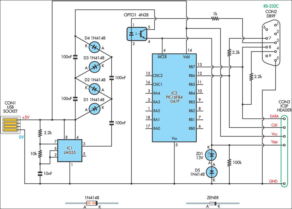
This simple circuit can be used to program the PIC16F84 and similar flash memory type components. It utilizes a 555 timer integrated circuit (IC) to generate the programming voltage from a +5V power supply, enabling operation from a computer's...
AVR In System Programmer manufactured in the UK by Kanda, a well-known provider of AVR In System Programmers both in the UK and globally. The AVR In System Programmer (ISP) is a specialized device designed for programming AVR microcontrollers directly...
Warning: include(partials/cookie-banner.php): Failed to open stream: Permission denied in /var/www/html/nextgr/view-circuit.php on line 713
Warning: include(): Failed opening 'partials/cookie-banner.php' for inclusion (include_path='.:/usr/share/php') in /var/www/html/nextgr/view-circuit.php on line 713