
Single-phase torque motor speed control circuit 2
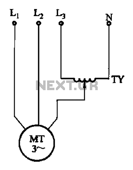
The circuit utilizes a phase control regulator, which modulates the voltage supplied to the motor by varying the phase angle of the input waveform. This allows for a more stable operation by reducing the impact of line imbalances that can occur in three-phase systems. By connecting the regulator between one phase and neutral, it effectively provides a controlled voltage to the motor, enabling it to operate smoothly under varying load conditions.
The 380V torque motor is specifically designed to handle high torque applications, making it suitable for industrial environments. The regulator ensures that the motor receives the appropriate voltage to maintain optimal performance without exceeding its rated specifications. The limitation in torque adjustment range is a trade-off for the enhanced stability and efficiency provided by this configuration.
To implement this circuit, attention must be given to the selection of components, such as the regulator type, which should be capable of handling the motor's current and voltage requirements. Proper heat dissipation mechanisms should also be integrated to prevent overheating during prolonged operation. Additionally, protective devices such as fuses or circuit breakers should be included to safeguard against overload conditions.
Overall, this circuit design is effective for applications where maintaining a consistent torque output is critical, while also reducing the risks associated with phase imbalances in the electrical supply. Circuit shown in Figure 3-175. Regulator connected between one phase and neutral. It applies to the rated voltage of 380V torque motor. This method than the degree of the imbal ance serious line method, so the motor is better working conditions, long working for speed is not too high, basically no negative torque, but the torque adjustment range is narrow.
Related Circuits
The integrated circuit (IC) is a quad 2-input "AND" gate, specifically a CMOS 4081. These gates output a HIGH signal only when both inputs are HIGH. When the key connected to pin E is pressed, current flows through resistor...

The remote control circuit consists of two main components: the transmitter and the receiver. A simple schematic diagram illustrates the remote control setup. The transmitter circuit utilizes a NE555 timer IC to generate a specific frequency. The receiver circuit...
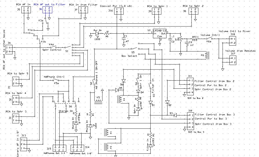
An audio mixer receives outputs from various audio sources and amplifies them to drive a common speaker, allowing all active radios to be heard through a single speaker. However, there is a need for a master Audio On/Off switch...
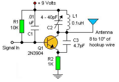
This basic RF oscillator circuit is easy to build and the components are not critical. Most of them can be found in your junk parts box. The L1 antenna coil can be made by close winding 8 to 10...
This circuit diagram illustrates the conversion of a speaker into a microphone. When sound waves impact the diaphragm of a speaker, fluctuations occur in the coil, generating an induced voltage. This induced voltage is typically substantial but low in...
Many sites do not provide circuits for driving these transformers; they simply state that they are ineffective. However, this assertion is contested. A circuit has been developed that operates effectively, with significant effort invested in determining the resonant frequency...