
Balanced Line Driver & Receiver
This project involves the conversion of unbalanced audio signals to balanced signals, which is beneficial for reducing noise and interference over long cable runs. The circuit can be implemented using operational amplifiers (op-amps) configured to create a differential signal from the unbalanced input. The unbalanced signal, typically carried over an RCA connector, is fed into an op-amp circuit where it is transformed into a balanced output suitable for XLR connectors.
The balanced line consists of two conductors carrying the same audio signal but with opposite polarity. This configuration allows the receiving end to reject any noise that may have been picked up along the cable, as the noise will likely affect both lines equally and can be canceled out. The circuit can also include a phantom power feature, which allows the remote device to be powered directly through the audio cables. This is achieved by injecting a low voltage DC signal, typically around 48V, onto the balanced lines, which can then be extracted by the microphone or other low-current devices at the receiving end.
For the implementation, the circuit design will include the following components:
1. Two op-amps for differential amplification.
2. Resistors to set the gain and balance the circuit.
3. Capacitors for filtering and stability.
4. A power supply circuit to provide the necessary voltage for the op-amps and phantom power.
The design should ensure that the op-amps are configured correctly to minimize distortion and maintain audio fidelity. The use of high-quality components is recommended to achieve optimal performance. Additionally, proper grounding techniques should be employed to further reduce noise and interference.
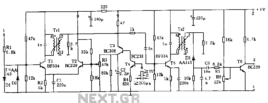
In conclusion, this project provides a practical solution for converting unbalanced audio signals to balanced lines, with the added capability of phantom powering, making it an excellent experiment for audio enthusiasts and professionals alike.With this simple project, you can have balanced lines too, simply adapting the unbalanced inputs and outputs of your hi-fi gear to become balanced, and then back to unbalanced at the other end. You can even be extra cunning, and power the remote converter from the cables carrying the signal. Professionally, this is called "Phantom Feed", and is used to power microphones and other low current equipment.
The version I have shown is actually a differential feed. Whilst not as good as a true 48V phantom powering circuit, it does work, and makes an interesting experiment (if nothing else). Before we start, a brief description of the standard (unbalanced) and balanced line is in order. An unbalanced line is the type you have on the hi-fi, typically using an RCA connector, and feeding the signal through a coaxial cable. The inner cable carrie 🔗 External reference
Related Circuits
This circuit drives up to four white LEDs in parallel from a 3.3V source and adjusts the total LED current from 1mA to 106mA in 64 steps of 1dB each. The circuit is designed for portable power applications that...
This is a fun and non-dangerous project for those people who like to throw projectiles magnetically. It simply works by placing a ferromagnetic projectile at one end of a coil and pulsing some power in it. The trick is...
The circuit operates at a voltage of 9V with a current consumption of only 5mA. It allows for frequency adjustment within the range of 150 to 180 kHz, featuring a bandwidth of approximately 20 kHz. This configuration ensures that...

The circuit demonstrates a method for powering CMOS integrated circuits (ICs) using RS-232C lines. The MAX680 is typically employed to generate a voltage equal to ±2 Vcc. This circuit operates in the opposite manner, accepting ±10.5 to ±12V from...
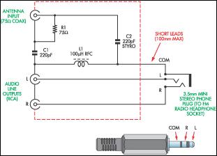
This document presents a concept for a low-cost adapter that enables the connection of a portable FM radio or MP3 player with an FM tuner to an external antenna and audio equipment, such as a hi-fi system or PC...
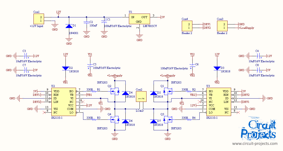
Assistance is required for a final year project involving the design of a grid-connected inverter. The focus is on developing a full bridge inverter circuit. The grid-connected inverter is a crucial component in renewable energy systems, particularly in solar photovoltaic...