
Based on 51 single-chip design and production of infrared remote control car
The infrared remote control car is designed with a focus on functionality and modularity, leveraging the AT89S51 microcontroller as the central processing unit. The microcontroller processes infrared signals received from the HT6221 remote control, which encodes commands into pulse-modulated signals. The remote control operates at a frequency of 38 kHz, emitting signals that are detected by the IR receiver module (1838). The receiver demodulates these signals and sends the output to the microcontroller's input port (P3.2), enabling the car to respond to the commands.
The L298 motor driver IC is employed to control the DC motors, allowing for bidirectional control and speed modulation. The L298 can handle high voltage and current, making it suitable for driving the motors of the car. The enable pins (ENA, ENB) control the activation of the motor outputs, while the input pins (IN1, IN2, IN3, IN4) determine the direction of rotation. The output pins (OUT1, OUT2, OUT3, OUT4) are connected to the motors, facilitating their operation. Additionally, protective diodes (IN5819) are included to safeguard the circuit from back EMF generated when the motors are stopped.
For obstacle detection and path tracking, a reflective coupler module is utilized. This module consists of an infrared emitter and a phototransistor, which work together to detect obstacles in the car's path. The LM324 voltage comparator is employed to analyze the output from the phototransistor, providing a high or low signal based on the presence of an obstacle. This information is relayed to the microcontroller, which can then adjust the motor operations accordingly, ensuring smooth navigation and obstacle avoidance.
Overall, the design incorporates a well-integrated hardware and software system, allowing for versatile control of the infrared remote control car. The combination of manual and automatic driving features, alongside robust obstacle detection capabilities, enhances the functionality and user experience of the device.An infrared remote control car, the AT89S51 microcontroller as the core controller, DC motor with L289 drivers work to control the operation of car in this section with infrared remote control manual car driving, autopilot, tracing forward and other functions in this The modular design of software using C language. T he AT98C51 microcontroller as the core, making a IR remote control car, car driving with automatic and manual features such as driving and tracking progress. Autopilot, the process can move forward obstacle avoidance. Manual driving, remote control car forward, backward, left turn, turn right, speed up other operations.
tracing the car can move forward in accordance with pre-designed path forward. The system consists of hardware and software components. Hardware to complete some of the major infrared transmitting and receiving coded signals, obstacle detection, path detection, the occurrence of DC motor operation functions. Software mainly to complete the signal detection and processing, device drivers and control and other functions.
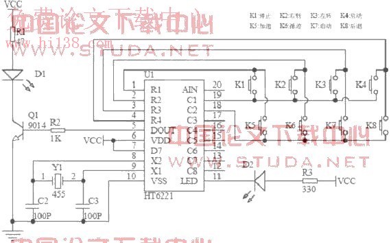
AT89S51 microcontroller infrared signal and decode the query, the query part of each input signal detection and appropriate treatment, including reversing the motor to determine whether an obstacle, to determine whether that payment in their car derailed and so on. system block diagram shown in Figure 1. The circuit of the main control device for the remote control chip HT6221, shown in Figure 2. HT6221 infrared pulse code modulated signal into 38KHZ by infrared emitting diodes infrared code sent in Figure 2 is the infrared emitting diodes D1, D2 is the key indicator, when a button is pressed light D2.
HT6221 encoding rule is: when a key is pressed more than 36ms, the chip oscillator enabled, if the button is pressed and the delay of about 108ms, 108ms launch this code from a start code (9ms), a result code (4. 5ms) low 8-bit address code (9ms ~ 18ms), high 8-bit address (9 ~ 18ms), 8-bit data code (9 ~ 18ms) and the 8-bit data number bit (9 ~ 18ms) form, if the key Press release not more than 108ms, then the code will only be launched from the start code (9ms) and the end code (2.
5ms) composed accordance with the connection on the map, K1 ~ K8 data codes are: 0x00, 0x01, 0x02, 0x03, 0x04, 0x05, 0x06, 0x07. The module uses an integrated IR receiver 1838, the circuit shown in Figure 3. Ceramic capacitor for the decoupling capacitor 104, DOUT is the output signal is demodulated, directly connected to the microcontroller ports P3.
2 there IR codes signal transmission, the output of the detector after the square wave signal shaping, and directly to the microcontroller. The module is mainly controlled by the IC L298 two motor rotating, and changing the motor speed, the circuit shown in Figure 4.
L298 chip is a high-voltage, high current queen bridge driver which SENSEA, SENSEB were two an H-bridge current feedback pin, when not directly grounded. VCC, VS is connected to the supply pin, the voltage ranges are 4. 5 ~ 7V, 2. 5 ~ 46V, design and microcontroller power supply terminal VCC terminal shared 5V supply, VS-side independent access 9V power supply.
ENA, ENB for the enable, low disables the output. IN1, IN2, IN3, IN4 for data input pin, OUT1, OUT2, OUT3, OUT4 as the data output pin. D1 ~ D8 are protected diode (IN5819, out for the release of the response generated when stopping the motor peak potential, otherwise it will Jihuai L298. Obstacle detection and track detection principle is the same from the economic point of view, the choice of the reflective coupler module, the circuit shown in Figure 5.
Optocoupler consists of a reflective infrared emission control components and a phototransistor. LM324 is a voltage comparator, when the level is greater than 3 feet 2 feet, the output 1 pin output high, otherwise the output low. high and low value depends on the level of LM324 to 2 feet, adjust 🔗 External reference
Related Circuits
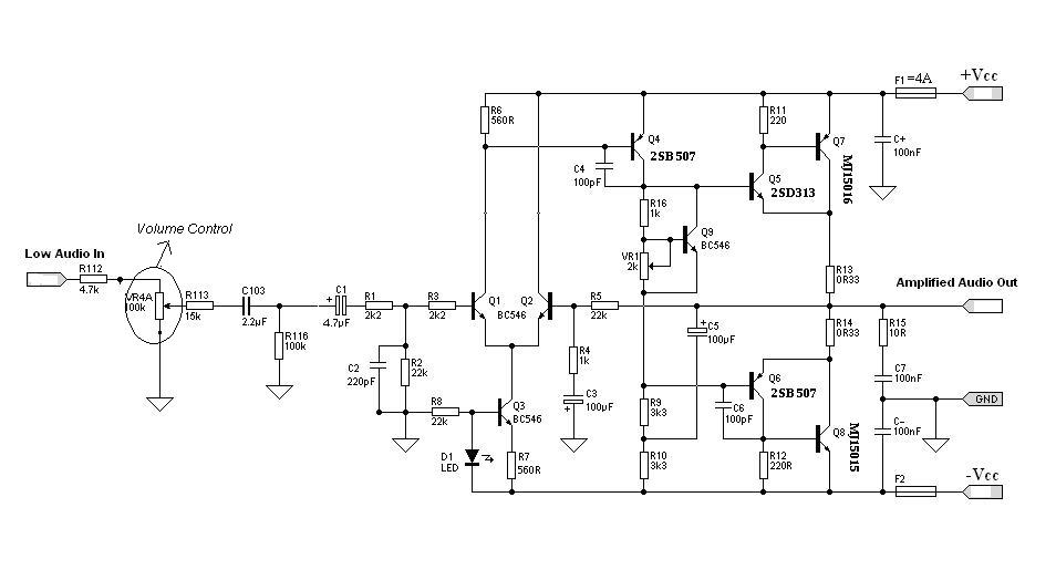
Designing an audio amplifier from scratch using discrete components is an engaging task, as it enables users to create amplifiers that meet diverse requirements. Audio amplifiers can enhance low-level sounds from mobile devices, making them louder and more vibrant....
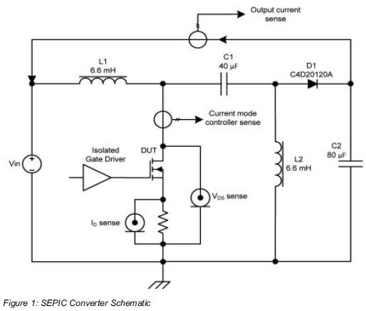
Comparing the performance of 1200V silicon carbide (SiC) MOSFETs with 1200V silicon MOSFETs and IGBTs at high frequency is essential to identify the differences in device losses and power-handling capabilities among these technologies. A demonstration platform has been developed...
This simple microcontroller circuit regulates a servo motor based on a 3-state switch. The servo motor functions as an actuator with three positions. It consists of three wires: one for VCC, one for ground, and a third for position...
The circuit described is recommended for SSTV applications utilizing a sound card connected to a computer. It follows the JVComm style of interface and can also be employed for RTTY and PSK31 applications. Many users modify this circuit to...
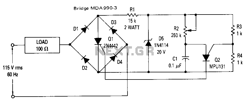
This circuit utilizes a Programmable Unijunction Transistor (PUT) for phase control of a Silicon Controlled Rectifier (SCR). The relaxation oscillator, created by Q2, manages the conduction of Q1, allowing control from 1 to 7.8 milliseconds or 21.6° to 168.5°....
The aim of this project was to get a digital camera into a small electric radio controlled (RC) aeroplane and still have it fly. The aeroplane shown, a park flyer, weighs between 400 and 550 grams depending on the...
Warning: include(partials/cookie-banner.php): Failed to open stream: Permission denied in /var/www/html/nextgr/view-circuit.php on line 713
Warning: include(): Failed opening 'partials/cookie-banner.php' for inclusion (include_path='.:/usr/share/php') in /var/www/html/nextgr/view-circuit.php on line 713