
Basic transistor amplifier circuits
The circuit design focuses on audio frequency applications, emphasizing the selection of component values that optimize performance within this range. Typical components may include resistors, capacitors, and inductors, which are chosen based on their ability to maintain signal integrity and minimize distortion.
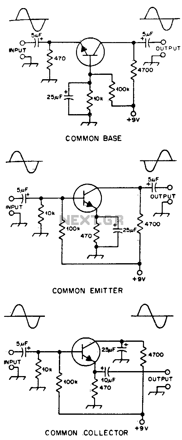
In audio circuits, the phase relationship between input and output signals is critical. This relationship can affect the overall sound quality and is often represented graphically. For example, in a simple audio amplifier circuit, the input signal may be a sine wave, while the output signal may experience a phase shift due to the reactive components in the circuit.
Component values are typically determined based on standard audio frequency ranges, which span from approximately 20 Hz to 20 kHz. Resistors may be selected to set gain levels, while capacitors and inductors are often used in filters to shape the frequency response. For instance, a low-pass filter may utilize a capacitor in series with the output to block high-frequency noise, ensuring that only the desired audio frequencies are amplified.
Furthermore, the schematic may include additional elements such as operational amplifiers, which can enhance signal processing capabilities. It is essential to analyze the input and output stages of the circuit to ensure that the phase relationships do not introduce unwanted artifacts, such as feedback loops or oscillations.
Overall, careful consideration of component selection and circuit design is vital in achieving optimal performance in audio frequency applications, ensuring that the circuit operates effectively within the specified frequency range while maintaining a clear and accurate representation of the audio signal.Typical component values are given for use at audio frequencies, where these circuits are used most often The input and output phase relationships are shown. 🔗 External reference
Related Circuits
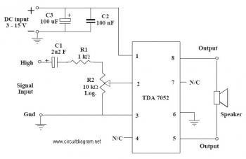
This is an audio amplifier circuit that uses the TDA7052 as the main component, along with five additional components to support its operation. The ideal supply voltage for this circuit is approximately 6-12V, and it does not require a...
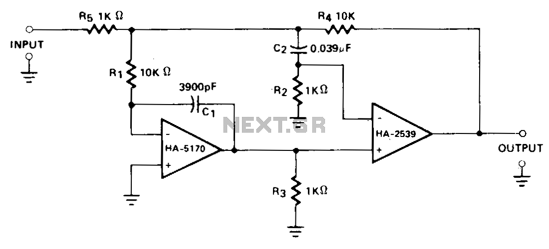
A composite configuration significantly reduces errors without compromising the high-speed, wideband characteristics of the HA-2539. The HA-2540 can also be utilized, although it exhibits slightly lower speeds and bandwidth response. The HA-2539 amplifies signals above 40 kHz, which are...
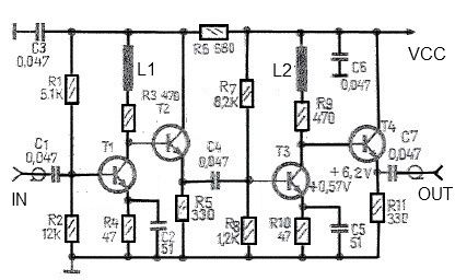
This antenna amplifier is effective for the frequency range of 35 kHz to 150 MHz. The circuit utilizes transistors and features a low 3 dB non-linearity along with a high gain of 43 dB. The input and output impedance...
This simple LED flasher circuit will alternately turn ON and OFF two LEDs. The first LED will illuminate when the second LED is OFF for a certain duration, and then the process will repeat. The LED flasher circuit operates using...
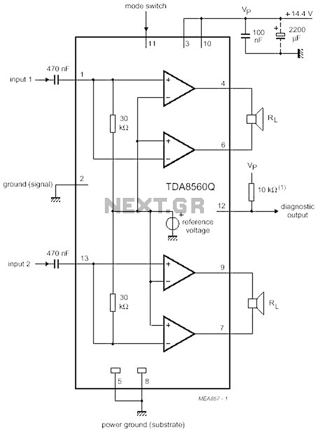
The proposed scheme is straightforward, requiring only a few external electronic components, making it suitable for car audio construction. The output power ranges from 2 to 4 Ohms, providing 2 x 30 W (with a maximum of 2 x...
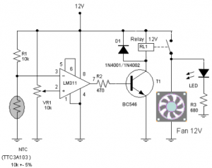
The circuit schematic diagram of a fan speed control system that activates only when necessary. When the transistor heats up, the fan will automatically turn on. The fan speed control circuit operates based on the temperature of the transistor, utilizing...