
Basic tracked robot with Targeting Laser pod Tutorials
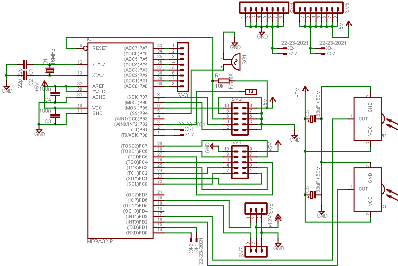
In this project, the ATMEGA16 microcontroller serves as the core processing unit, operating at a frequency of 16MHz. This microcontroller is well-suited for various robotic applications due to its versatility and sufficient processing power. A distinctive feature of this robot is the battery monitoring system, which is implemented using the Dallas Semiconductor DS2438 chip. This chip's capabilities include monitoring current and voltage levels, as well as temperature, which are critical for managing the power supply of the robot. This feature is particularly valuable in ensuring that the robot operates within safe voltage levels, preventing unexpected shutdowns due to battery depletion.
The navigation system is designed to be straightforward, utilizing an infrared pair consisting of a TSOP1907 receiver and several IR LEDs. This setup allows the robot to detect obstacles and navigate its environment effectively. The potential addition of sonar technology would enhance the robot's navigational capabilities, providing more precise distance measurements and obstacle avoidance.
The physical construction of the robot emphasizes stability and weight distribution. The low-profile design aids in maneuverability, while the strategic placement of the battery toward the front enhances the robot's ability to ascend inclines. The integration of servos into the locomotion system significantly improves performance, as the original mechanism was inadequate for the demands of the robot. The wheels have been carefully modified to ensure a secure fit, enhancing durability and reliability during operation.
The battery holder design is functional yet straightforward, utilizing a PCB to secure the batteries in place. This method allows for easy access and replacement of batteries while maintaining a low center of gravity, which is essential for the robot's overall balance and performance. The careful consideration of weight distribution and component placement will contribute to the successful operation of the robot in various environments.In this project we`ll be using the ATMEGA16 @16MHz. But as every project. it must have something special, something to be able to look different from other. But what I `ve seen many robots with photosensors (photovore, photophobe), many linefollowers, many object avoiders, some heat seakers, sumobots, micromouse and others. BUT, very few had a battery monitor. Most of them run on a new or freshly recharged battery. If the battery was drained and wasn`t simply enough capasity to feed the robot That`s why I incorporate a Dallas Semi DS2438 in my circuit board. I don`t like usually to advertise but this chip had everything. A current sensor, a voltage sensor, a thermometer and so other goodies we won`t be needing. Now navigation. Since it`ll be a simple navigator - free roaming robot (with some extra features) I`ll be using a simple IR_pair for the robot, but if I have time (aaa exams exams exams exams they are killing me!) I`ll also include a Sonar.
The pair will consist of a TSOP1907 and some single IR Leds. And now it`s picture time. Since I have assebled the case years ago and don`t like to rip it up right now. I`ll be showing some basic pictures of the case of the robot explaining how it was built and which are the thoughts for the future =P. And here is the front view of the robot. As you can see the case is quite close to the ground but our subject here is not machining clearly but programming the robot behaviors.
Here is the bottom view of the robot. It used to be used as a place for the batteries but as experience grow it teaches me to place the battery (and any other heavy thing) in the front of the robot to be able to climb hills with easy. But more details coming. And here is the machining tips for the wheels! I got some servo cross-like horns cutted `em to fit the inner of the wheel, placed a screw in an empty hole of the wheel and glue it for safety with some super glue!
And finish. Also I kept the outter axis of the wheel (it was there from the time I bought this poor toy) and after shorting it a little, I fitted it back in. So the Case and the wheels are bond together making the locomotion system more stample than ever. NOTE: that the locomotion system that was with the toy was extremely weak that`s why I placed in the servos!
Finally, and also very important, after mounting the servos to the case I jointed `em with that golden pipes (don`t know how to call `em sorry). And here we are. the locomotion system and the case in finished! Now it`s batteries` time. And now the hardest part for me. mounting the batteries. Batteries usually are the heaviest part of a robot. Because we have a tracked robot, placing the batteries in the front is crusial for the balancing of our robot and it`s ability to climb step hills!
I hane the robot balancing it`s weight at about the middle of the robot so it`s just very ok! As you can see the holder is very simple just a part of a pcb mounted to the case with some screws and glue and so long pin headers to hold the battery. So with the battery, it should look like that: And now the big deal. The electronics. I have been trying to use two microcontroller since the beginning but always something was about the fail.
LCD fail, IR fail, 🔗 External reference
Related Circuits
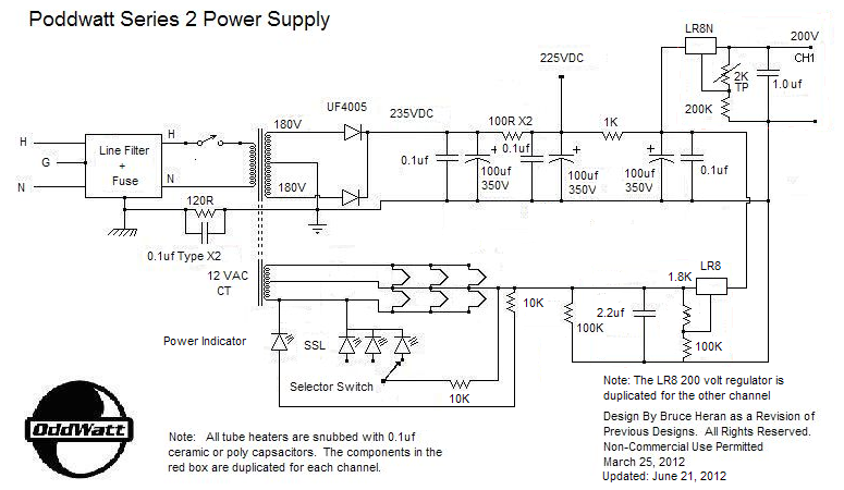
This project is related to previous tube amplifier designs, particularly the first Push-Pull EL84 (6BQ5) Oddwatt project from nearly two years ago. Both projects utilize EL84 / 6BQ5 tubes; however, while the earlier version employed an ECC802S driver, this...
Most components have been assembled for the electrical aspect of the project. Serial communication is nearly operational and will utilize a Teensy 2.0 chip to communicate via serial USB with the Mega128. A TTL UART serial driver, such as...
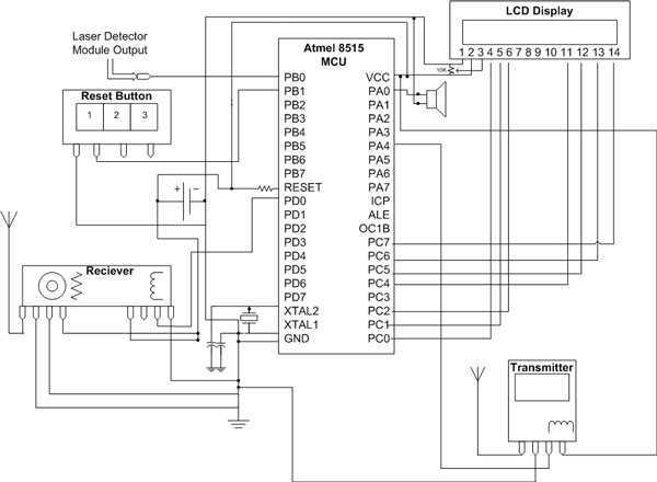
The hardware for this project had three main components: laser gun assembly, detector unit, control pad. The detector unit's function was to simply detect a laser pulse over a small area sent by the laser driver circuit on the...
The Tiny Audio Amplifier kit is a good choice for battery operation. It is based on LM386 IC. Power supply - 6 - 12 VDC. Output power - 1 W, 8 Ohm. The quiescent power drain is only 24...
BEAM enthusiasts often quickly learn to scavenge necessary components for their projects from technoscrap. However, there will always be occasions when purchasing new parts or materials becomes essential. This trend is increasingly prevalent as Application Specific Chips are being...
A phase-locked loop (PLL) is a servo system, or a feedback loop that operates with frequencies and phases. PLLs are known to be quite useful in communication systems, where they can extract small signals from significant noise. This discussion...