
Basic UPS Power Supplys
This circuit functions as a versatile UPS solution, capable of maintaining a stable output under varying conditions. The integration of a transformer, appropriate fuses, and diodes ensures safe operation and protection against common electrical faults. The design's adaptability allows for the use of different battery types and voltage regulators, making it suitable for various applications where uninterrupted power is critical. The implementation of a trickle charging mechanism protects the battery from overcharging, thereby extending its lifespan and reliability. The careful selection of components, such as the slow-blow fuse and specific diodes, enhances the circuit's resilience against short circuits and power failures. Overall, the circuit provides a reliable means to ensure continuous power supply, making it an essential component in environments where power stability is paramount.This circuit is a simple form of the commercial UPS, the circuit provides a constant regulated 5 Volt output and an unregulated 12 Volt supply. In the event of electrical supply line failure the battery takes over, with no spikes on the regulated supply.
This circuit can be adapted for other regulated and unregulated voltages by using different re gulators and batteries. For a 15 Volt regulated supply use two 12 Volt batteries in series and a 7815 regulator. There is a lot of flexibility in this circuit. TR1 has a primary matched to the local electrical supply which is 240 Volts in the UK. The secondary winding should be rated at least 12 Volts at 2 amp, but can be higher, for example 15 Volts. FS1 is a slow blow type and protects against short circuits on the output, or indeed a faulty cell in a rechargeable battery.
LED 1 will light ONLY when the electricity supply is present, with a power failure the LED will go out and output voltage is maintained by the battery. The circuit below simulates a working circuit with mains power applied: Between terminals VP1 and VP3 the nominal unregulated supply is available and a 5 Volt regulated supply between VP1 and VP2.
Resistor R1 and D1 are the charging path for battery B1. D1 and D3 prevent LED1 being illuminated under power fail conditions. The battery is designed to be trickle charged, charging current defined as :- D2 must be included in the circuit, without D2 the battery would charge from the full supply voltage without current limit, which would cause damage and overheating of some rechargeable batteries. An electrical power outage is simulated below: The ability to maintain the regulated supply with no electrical supply depends on the load taken from the UPS and also the Ampere hour capacity of the battery.
If you were using a 7A/h 12 Volt battery and load from the 5 Volt regulator was 0. 5 Amp (and no load from the unregulated supply) then the regulated supply would be maintained for around 14 hours. Greater A/h capacity batteries would provide a longer standby time, and vice versa. 🔗 External reference
Related Circuits
The Kill A Watt is a product that measures volts, amps, and power factor of individual appliances, allowing users to calculate power consumption and running costs. However, a desire for a solution that provides similar data for an entire...
This is a simple NiCd battery charger powered by solar cells. A solar cell panel or an array of solar cells can charge a battery at more than 80% efficiency, provided the available voltage exceeds the fully charged battery...
The TDA2549 is a complete intermediate frequency (IF) circuit that includes automatic frequency control (AFC), automatic gain control (AGC), demodulation, and video preamplification capabilities for multistandard television receivers. It can process both positively and negatively modulated video signals in...
When the infrared receiver tube PH302 receives a signal from the remote control, the CX20106A selected frequency amplifier outputs a low-frequency signal. The low-level signal charges capacitor C through diodes D and R, causing the negative side potential of...
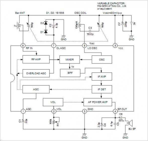
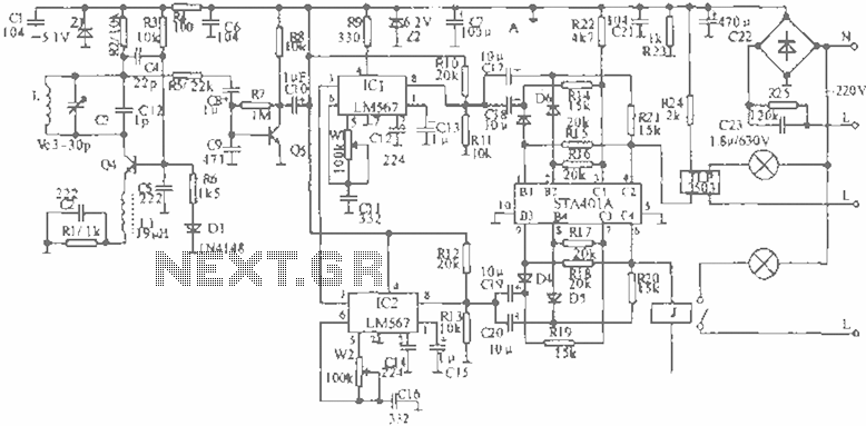
The CXA1619BM and CXA1619BS are one-chip FM/AM radio integrated circuits developed by Sony Corporation. These ICs are intended for use in radio-cassette tape recorders and headphone tape recorders, offering a variety of functions. The CXA1619BM and CXA1619BS are designed to...
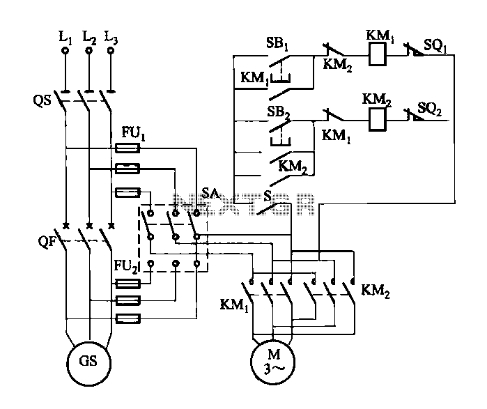
FIG M is a variable speed motor control for the opening and closing of a wicket gate. It features an electric governor. The system is activated by a power switch (SA) located on the front grid, and a toggle...
Warning: include(partials/cookie-banner.php): Failed to open stream: Permission denied in /var/www/html/nextgr/view-circuit.php on line 713
Warning: include(): Failed opening 'partials/cookie-banner.php' for inclusion (include_path='.:/usr/share/php') in /var/www/html/nextgr/view-circuit.php on line 713