
Basic Timer Control with NE555
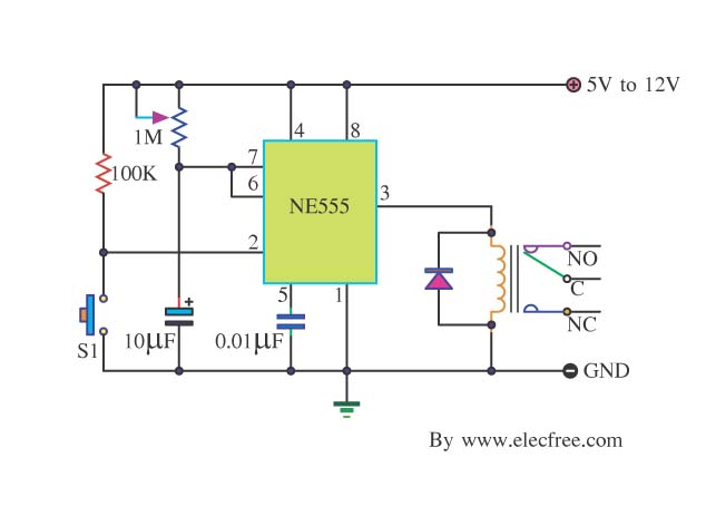
The IC 555 timer is a versatile and widely utilized component in electronics, functioning primarily in astable, monostable, and bistable modes. In its astable configuration, the IC 555 can generate a continuous square wave output, making it ideal for applications such as clock pulses, tone generation, and LED flashing. The frequency of oscillation is determined by two external resistors and a capacitor connected to the circuit, allowing for easy adjustments to the timing characteristics.
In monostable mode, the IC 555 can produce a single output pulse of a specified duration in response to an external trigger. This configuration is commonly used in timers, pulse width modulation, and event counting applications. The duration of the output pulse is controlled by the values of a resistor and capacitor connected to the circuit.
The bistable mode allows the IC 555 to act as a flip-flop, maintaining its output state until triggered by an external signal. This feature is useful in applications such as toggle switches and memory storage.
The IC 555 is available in various package types and can operate over a wide range of supply voltages, typically from 4.5V to 15V. Its ease of use, reliability, and low cost have made it a staple in both educational and professional electronic projects. Proper understanding of the timing equations and component selection is essential for optimizing the performance of circuits utilizing the IC 555.As friends many take an interest the circuit about IC 555 which be integrated highly popular that circuit. I then lead the circuit sets the time be Basic. 🔗 External reference
Related Circuits
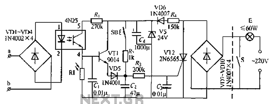
An automatic light system is integrated with a telephone block system. When the phone rings, the owner is prompted to pick up the handset or pull a lever, causing the lamp to light up. If there is no contact...
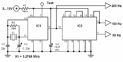
This circuit generates a 50 Hz timebase signal that is independent of the power line frequency. It is designed to provide the 50 Hz signal for electronic circuits that operate specifically with this clock frequency, primarily for circuits and...
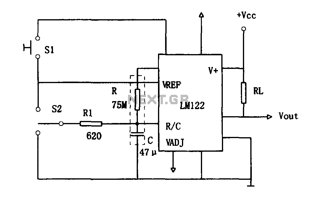
As illustrated in Figure 1, the circuit utilizes an LM122 timer. The circuit's start, reset, and stop functions are managed through switching operations. Switch S1 initiates the timing sequence when the timer is activated; thereafter, this switch has no...
The anti-theft system includes two frequency sirens connected to the vehicle's immobilizer system. In the laboratory simulation model, the changes in operating modes, siren activation, and fuel supply cut-off are indicated by the illumination of LEDs and communicated to...
Power pulse circuit using LM350 and NE555. This circuit can be used to drive lamps, power LEDs, DC motors, etc. Adjust R5 for output amplitude and R1 for output power. The LM350 is an adjustable 3-terminal voltage regulator. The power...
This relay circuit is controlled by nearly any type of infrared remote controller. It operates under the assumption that most remote controllers utilize high-frequency modulated infrared light. By filtering out unmodulated or low-frequency modulated signals, this circuit effectively eliminates...
Warning: include(partials/cookie-banner.php): Failed to open stream: Permission denied in /var/www/html/nextgr/view-circuit.php on line 713
Warning: include(): Failed opening 'partials/cookie-banner.php' for inclusion (include_path='.:/usr/share/php') in /var/www/html/nextgr/view-circuit.php on line 713