
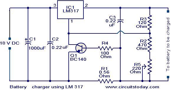
Battery charger circuit using LM317
The battery charger circuit using the LM317 is structured to provide a reliable and efficient charging solution for 12V lead-acid batteries. The LM317 is favored for its ease of use and versatility in voltage regulation, making it suitable for various applications, including battery charging.
The circuit's operational efficiency hinges on the correct selection and configuration of its components. The transistor Q1 plays a crucial role in regulating the output current and voltage. Resistor R1 is essential for limiting the current during the initial charging phase, preventing excessive current that could damage the battery. The inclusion of potentiometer R5 allows for fine-tuning of the charging voltage, enabling the user to set the output voltage according to the specific requirements of the battery being charged.
When the battery is connected, the initial current flow through R1 leads to an increase in the output voltage from the LM317, which is sensed by the battery. As the battery charges, the voltage across it rises, and once it reaches a predetermined level, the LM317 reduces the output current. This automatic adjustment is critical for maintaining the health of the battery, as it prevents overcharging, which can significantly reduce battery lifespan.
The design requires an input voltage that exceeds the output voltage by at least 3V to ensure proper regulation by the LM317. This voltage drop is a characteristic of the LM317, and it is essential to account for it when selecting the power supply. The choice of an 18V DC input is appropriate, providing sufficient headroom for the LM317 to operate effectively while delivering the required charging voltage to the battery.
Overall, this LM317-based battery charger circuit is a practical solution for charging lead-acid batteries, combining simplicity with functionality. Its design allows for easy assembly and adjustment, making it accessible for hobbyists and professionals alike.Here is a simple but effective battery charger circuit using IC LM 317. The circuit can be used to charge 12Vlead acid batteries. The circuit is very simple and can be easily assembled on a general purpose PCB. The heart of the circuit is IC LM 317, which is an adjustable voltage regulator IC. The pin 1 of the IC is the control pin which is used to c ontrol the charging voltage. The pin 2 is the output pin at which the charging voltage appears. The pin 3 is the input pin to which the regulated DC supply is given. The charging voltage and current is controlled by the Transistor Q1, resistor R1 and POT R5. when the battery is first connected to the charging terminals, the current through R1 increases. This in turn increases the current and voltage from LM 317. When the battery is fully charged the charger reduces the charging current and the battery will be charged in the trickle charging mode. The input voltage to the circuit must be atleast 3V higher than the expected output voltage. LM 317 dissipates around 3V during its operation. Here I used 18V DC as the input. 🔗 External reference
Related Circuits
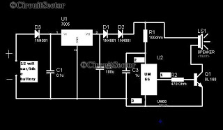
A simple musical horn circuit designed for use in cars or motorcycles can be connected to the 12V battery of any vehicle. This circuit is commonly utilized as a reverse musical horn. It employs the low-cost musical integrated circuit...
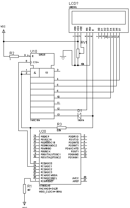
This is not a new idea for interfacing an LCD using two wires, but it can be beneficial in situations where there are insufficient microcontroller pins. This example is based on the Hitachi 44780 alphanumeric LCD. The provided circuit...
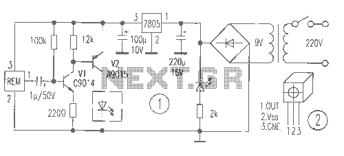
The receiver provides two TV signals, one for the living room and another for the bedroom, along with a satellite receiver. Watching television in the bedroom is convenient in Taiwan; however, when watching television in the living room, it...

Phase noise is a critical performance parameter of frequency synthesizers for wireless applications. RF system designers of phase-modulated cellular systems, such as PHS, GSM, and IS-54, require low noise local oscillator (L.O.) or frequency synthesizer blocks. This document describes...
This LED flasher circuit is similar to the previous transistor-based LED flasher but utilizes a 555 integrated circuit as the primary component. The schematic diagram illustrates an LED flasher circuit that produces alternating LED flashing, with distinct flashing periods...
A device that conducts electric current and converts electrical energy into another form. Power consumed by a device or circuit while performing its function can be represented by a resistor and capacitor. The capacitor in the load circuit represents...