
Switchless NiCd-NiMH Battery Charger
The circuit utilizes an LM317 voltage regulator configured as a constant current source, which is ideal for charging NiCd batteries. The absence of a fixed or variable resistor at the ADJ pin simplifies the design and reduces component count while ensuring that the output current remains stable. The use of R1 to set the charging current allows for a straightforward calculation based on the desired charging rate, which is critical for maintaining battery health and longevity.
The transistor T1 acts as a switch that is turned on by the voltage developed across R1 when a battery is connected. This mechanism ensures that the charger only activates when a battery is present, preventing unnecessary power consumption. The inclusion of diode D1 serves as a protective component that maintains the necessary biasing of the transistor while also allowing for efficient current flow into the battery.
Diode D4 provides an essential safety feature by blocking reverse current flow from the battery to the charger, which could potentially damage the circuit or lead to battery discharge when the charger is not powered. This feature is crucial for maintaining the integrity of the charging process and ensuring that the batteries are not inadvertently drained.
The design's reliance on R(n) for current regulation emphasizes the importance of selecting appropriate resistor values to achieve the desired charging current, which should be carefully calculated based on the specific battery capacity. The guideline of charging at one-tenth of the nominal capacity is a standard practice that helps to prevent overheating and prolongs the battery's lifespan.
When considering power dissipation in the resistors, it is vital to ensure that they can handle the thermal load generated during operation, especially at higher charging currents. This consideration is crucial for maintaining circuit reliability and preventing component failure.
Finally, the recommendation for using a small heat sink with the LM317 is a prudent measure to enhance thermal management, ensuring that the regulator operates within safe temperature limits. The preference for a general-purpose mains adapter over a transformer/rectifier combination highlights the importance of safety and ease of use in practical applications, making this circuit a robust solution for charging NiCd batteries effectively.This circuit may be used to replace the single current limiting resistor often found in dirt cheap battery chargers. The alternative shown here will eventually pay off because you no longer have to throw away your NiCds after three months or so of maltreatment in the original charger.
The circuit diagram shows an LM317 in constant-current configur ation but without the usual fixed or variable resistor at the ADJ pin to determine the amount of output current. Also, there is no switch with an array of different resistors to select the charge currents for three cell or battery types we wish to charge: AAA, AA and PP3 (6F22).
When, for example, an empty AAA cell is connected, the voltage developed across R1 causes T1 to be biased via voltage dropper D1. This results in about 50 µA flowing from the LM317`s ADJ pin into the cell, activating the circuit into constant-current mode.
D4 is included to prevent the battery being discharged when the charger is switched off or without a supply voltage. The charging current I is determined by R1/R3/R3 as in R(n) = (1. 25 + Vsat) / I where Vsat is 0. 1 V. The current should be one tenth of the nominal battery capacity ” for example, 170 mA for a 1700-mAh NiCd AA cell.
It should be noted that PP3` rechargeable batteries usually contain seven NiCd cells so their nominal voltage is 8. 4 V and not 9V as is often thought. If relatively high currents are needed, the power dissipation in R1/R2/R3 becomes an issue. As a rule of thumb, the input voltage required by the charger should be greater than three times the cell or battery (pack) voltage.
This is necessary to cover the LM317`s dropout voltage and the voltage across R(n). Two final notes: the LM317 should be fitted with a small heat sink. With electrical safety in mind the use of a general-purpose mains adapter with DC output is preferred over a dedicated mains transformer/rectifier combination. 🔗 External reference
Related Circuits
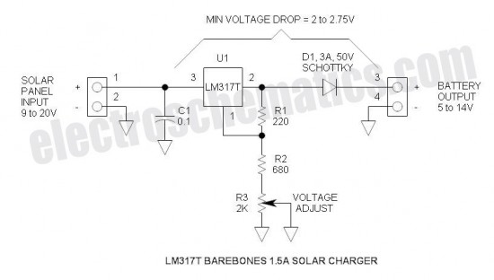
This is the simplest and most affordable solar battery charger that a hobbyist can create. It has some drawbacks compared to other similar controls, but offers unique advantages. The solar battery charger circuit is designed to harness solar energy to...
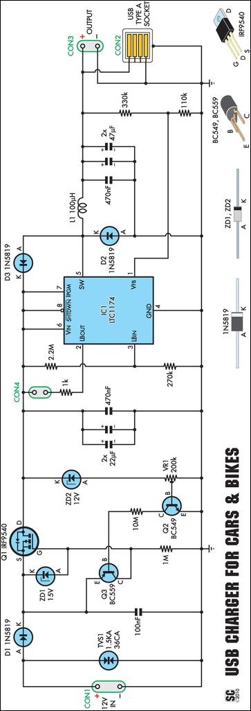
An efficient USB charger designed to operate from a 12V car battery, achieving up to 89% efficiency and capable of charging USB devices at currents up to 525mA. It does not drain the battery if left permanently connected, provided...
Camping today often requires various electronic devices for daily activities and entertainment. Typically, a charged lead-acid battery and a power inverter are utilized to ensure a well-organized trip, allowing family members to enjoy their electronic equipment. It is essential...
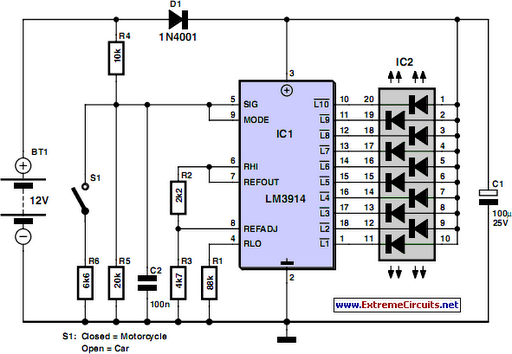
As the circuit operates, the three sets of diodes with their isolation capacitors build up an increasing voltage on capacitor C1. The voltage at point B will also increase and be about twelve volts less than the voltage on...
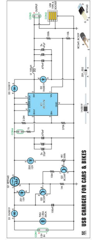
Seeking an efficient USB charger capable of operating from a 12V car battery? This unit operates at up to 89% efficiency and can charge USB devices effectively. This USB charger circuit is designed to convert a 12V car battery supply...
The following diagram represents the schematic of a Ni-CAD battery charger circuit, which features current and voltage limiting to prolong the battery's lifespan. The lamp L1 will illuminate brightly while the LED will be off when the battery is...