
Battery charging regulator

The circuit operates by initially applying a charging voltage to a 12-volt battery. The charging current is regulated to a maximum of six amperes to prevent overheating and damage to the battery during the charging process. The SCR (Silicon Controlled Rectifier) serves as a key component in this circuit, acting as a switch that controls the flow of current to the battery. When the battery voltage reaches its fully charged state, the SCR is turned off, effectively halting the main charging current.
To maintain the battery's charge without overcharging, a trickle charge is introduced. This is achieved through a resistor denoted as R4 in the circuit. The value of R4 is critical, as it determines the amount of current that continues to flow into the battery after the SCR has been deactivated. The trickle charge serves to keep the battery topped off without risking damage from excessive voltage.
The circuit can be designed to accommodate a range of voltages and currents beyond the specified 12 volts and six amperes. With appropriate modifications, it can handle voltages from 6 to 600 volts and currents up to 300 amperes, making it versatile for various applications. This adaptability is achieved through the careful selection of components, including the SCR and resistors, to ensure they can safely manage the desired electrical parameters.
Overall, this charging circuit is a robust solution for maintaining battery health and longevity, utilizing both a primary charging phase and a secondary trickle charge phase to optimize battery performance.The circuit is capable of charging a 12 volt component selection. When the battery voltage battery at up to a six ampere rate Other volt- reaches its fully charged level, the charging ages and currents, from 6 to 600 volts and up to SCR shuts off, and a trickle charge as deter-300 amperes, can be accommodated by suitable mined by the value of R4 continues to flow.
Related Circuits
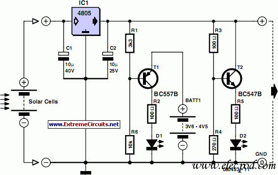
This device is designed to be a simple, inexpensive comparator intended for use in a solar cell power supply setup where a quick "too low" or "just right" voltage indicator is needed. The circuit consists of one 5V regulator,...
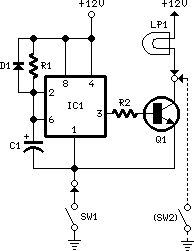
When the door is opened, SW1 closes, powering the circuit and turning on the lamp. C1 begins to charge slowly through R1, and when the voltage at pins #2 and #6 of IC1 reaches 2/3 of the supply voltage,...
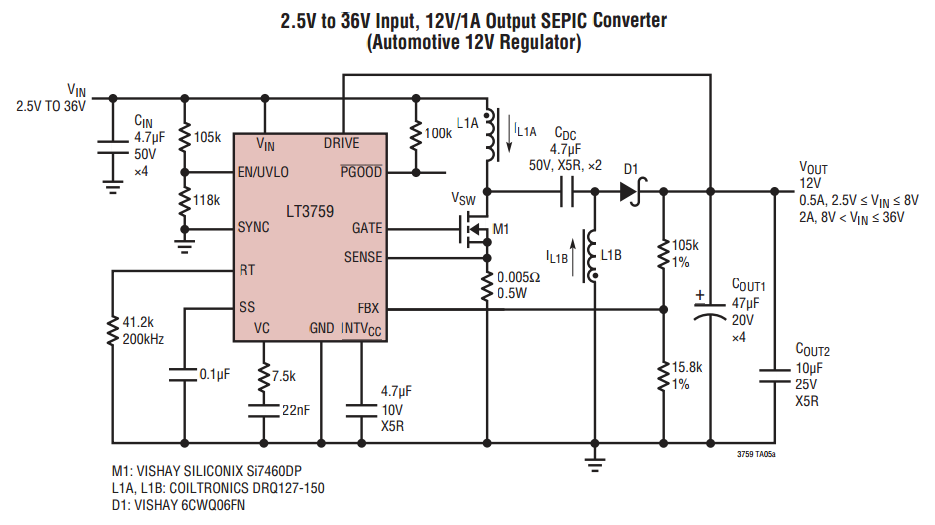
When VOUT is very low during startup or in the event of a short-circuit fault at the output, the switching regulator must operate at low duty cycles to keep the power switch current within the current limit range. This...
This circuit is designed to monitor the voltage level of a car battery. When the battery voltage drops to 11.5V or less, the transistor Q1 is activated, causing LED D1 to illuminate. When the battery voltage is between 11.5V...
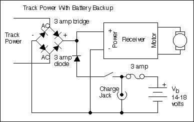
The primary motivation for utilizing battery power for trains is to eliminate the need for track cleaning and wiring. Track maintenance can pose significant challenges. Incorporating radio control into a battery-powered system enhances command control, an advantageous feature. In...
Battery Indicator Circuit for the Caravan. This i-TRIXX circuit can prevent a lot of trouble for those who go on holiday in a caravan. It would be a significant damper on your holiday spirit when you are unprepared. The Battery...