
BATTERY MONITOR

A comprehensive electronic schematic for this battery monitoring system involves several key components and design considerations. The circuit is centered around a microammeter that measures the current flow through a series of current-limiting resistors, which are connected directly to each battery terminal. This arrangement ensures that even in the event of a short circuit, the current remains at a safe level, thereby minimizing shock hazards and fire risks.
The rotary switch, while initially included, is replaced with dedicated measurement circuits for each battery. Each circuit consists of its own microammeter and calibration potentiometer, allowing for individual battery monitoring without the need for a multi-position switch. This design enhances safety by eliminating any potential confusion or error associated with switch positions.
The bar graph display, utilizing the Densitron LM4064 LCD, is interfaced with a microcontroller that continuously reads the voltage levels from each battery circuit. The microcontroller processes these readings and dynamically adjusts the height of each corresponding bar on the LCD. This real-time display provides immediate feedback on the health of each battery, allowing users to quickly identify any issues.
The design also incorporates a protective enclosure for the circuit components, shielding them from environmental factors and ensuring long-term reliability. Additionally, the layout is optimized for minimal space usage on the dashboard while maintaining accessibility for calibration and maintenance.
Overall, the schematic design prioritizes safety, efficiency, and user-friendliness, making it an effective solution for monitoring multiple batteries in an electric vehicle context.Figure 1 is a schematic of such an arrangement with four batteries. The diagram in Figure 2 uses one voltmeter and a two-pole multi-position rotary switch to select the battery to monitor. While accomplishing the goal of bringing the metering of batteries out of the battery compartment, this design has some safety problems.
A direct connection to any point in the battery pack is dangerous because of the shock hazard and also because a short-circuit could result in injury or fire. The risks can be reduced by revising the design as shown in Figure 3. By placing current limiting resistors right on the battery terminals, only micro amperes are allowed to flow on the wires of the instrument, even in the case of a short circuit.
Note that the meter itself is not a voltmeter but is a micro ammeter with a scale marked in Volts. If the switch is eliminated by providing separate meters for each battery, then the batteries can be compared under identical load conditions. In 1989, I installed just such a meter system in my Sebring-Vanguard Citicar. The dashboard sported eight vertical panel meters, one for each 6-Volt battery. I included trimmer potentiometers behind the dash to provide calibration of the meters. Figure 4 is the circuit diagram for one meter. These meters did an excellent job in the Citicar. It was easy to spot a weak battery and individual cell failures were immediately evident by the 2-Volt drop in the meter.
I wanted to have similar metering in the Solectria Force. The dashboard appearance of the Force would suffer if I installed thirteen meters of any sort. But there is room in the instrument cluster for one small instrument. I decided to make a display which could show all 13 batteries at once in bar graph format. So the challenge was to design something that could continuously display the voltage of each battery altogether in a compact space on the dashboard. Figure 5 shows what I had in mind. The numbering below the bars identifies each battery. The numbers 1 to 8 identify the batteries in the rear set and the letters A through E identify the five batteries under the hood.
The height of a bar indicates the terminal voltage of that battery. The display is "live" so that a change in battery voltage results in a corresponding change of bar height. In the example above, battery C has low voltage. I evaluated several alternatives before settling on a design. My goal was to build a system that is simple, safe, cheap, reliable, accurate, and responsive. As with any design, there were some tradeoffs to be made. The resulting design met most of my goals. I will describe a few of the reasons that I made certain design choices. It is difficult to find a display that will fulfill my idea for a bar graph display. I considered using some sort of LED bar graph unit as found on some stereo systems. Eventually, I located a liquid-crystal display of the proper size for the dashboard installation. This display, a Densitron LM4064, i 🔗 External reference
Related Circuits
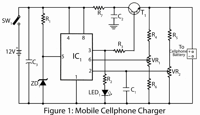
This project utilizes common electronic components to create a mobile battery charger using AA cells. The primary component of the circuit is the NE555 timer IC, which is responsible for charging and monitoring the voltage level. The control voltage...
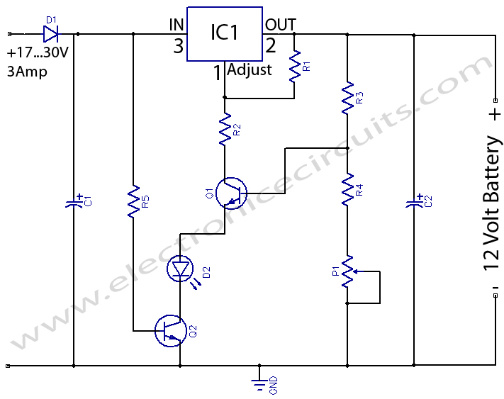
12 Volts Lead Acid Battery Charger Circuit. Apart from serving as a standard battery charger, this circuit is ideal for providing a constant charge to a 12-Volt lead-acid battery. This 12-Volt lead-acid battery charger circuit is designed to efficiently charge...
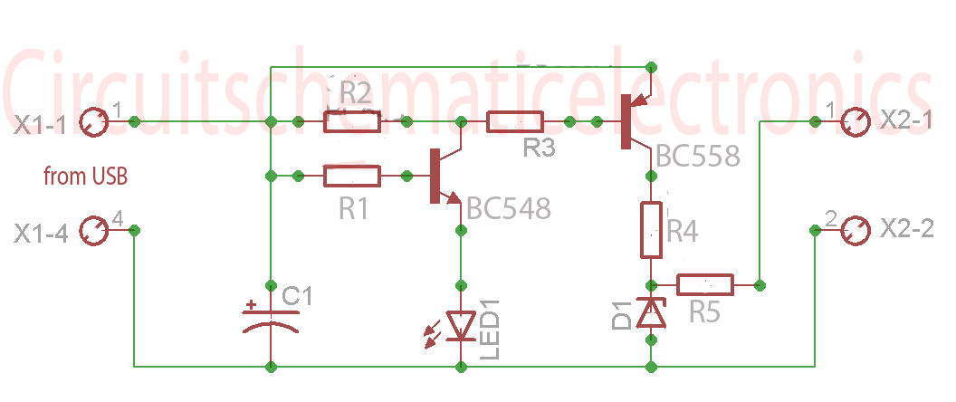
This is a simple circuit for automatic switchover between battery and USB port. This circuit uses a more general step-up converter architecture. The circuit designed for automatic switchover between a battery and a USB power source employs a step-up...
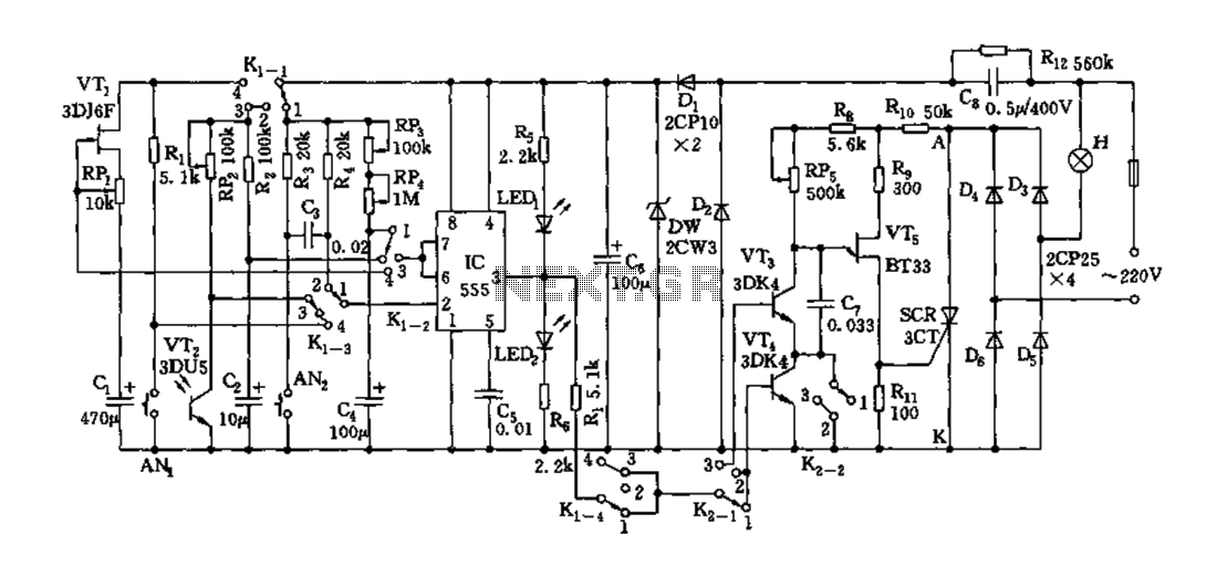
Depending on the external circuit connection, the 555 timer can be configured for various modes such as start delay, trigger delay, multi-harmonic oscillation, and other operational conditions. It functions as a versatile tester with the inclusion of some RC...
Without a USB to phone battery charger circuit, charging a phone battery using a USB port on a computer can quickly damage the battery, resulting in bulging. This occurs because the voltage output from USB is 5 volts, while...
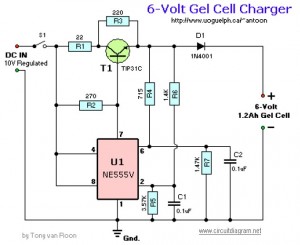
This circuit requires a regulated 10V DC front end capable of supplying 2 Amps. It begins the charging period at 240mA and automatically switches to a float condition (trickle charge) of 12mA when fully charged. The capacitors should be...