
6V Gel Cell Battery Charger
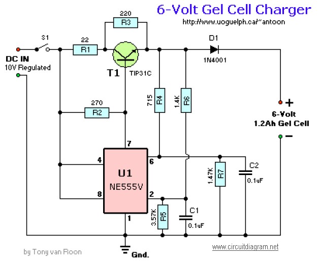
The battery charger schematic for a 6V Gel Cell battery type is designed to efficiently manage the charging process of rechargeable lithium batteries. The circuit utilizes a constant current approach, delivering 60 mA to AA cells until a voltage threshold of 2.4V per cell is reached. This method ensures that the batteries are charged safely and effectively, preventing overcharging, which could damage the cells. The inclusion of resistors such as R1 through R7 and capacitors C1 and C2 helps to stabilize the circuit and filter any noise, contributing to a smooth charging operation.
The Lead-Acid battery charger circuit complements the Gel Cell design by providing an initial charging voltage of 2.5V per cell at a temperature of 25°C. This initial voltage is crucial for quickly bringing the battery up to a functional charge level. As the battery charges, the circuit is designed to reduce the output voltage automatically when the charging current drops to 180 mA, further safeguarding the battery's health and extending its lifespan.
The solar-powered mobile phone battery charger is another innovative design that allows for charging from a lower voltage source, such as a solar panel. This circuit is particularly valuable in off-grid applications, where conventional power sources are unavailable. Care must be taken to ensure that the voltage produced by the solar panel exceeds that of the battery being charged, as attempting to charge with equal or lower voltage could lead to inefficiencies or damage.
The 12V NiCAD battery charger operates with a charging rate of 200 mA/hour, beginning at 75 mA until the battery reaches full charge. This gradual approach minimizes stress on the battery cells, allowing for a complete recharge within approximately four hours. The trickle charging phase ensures that the battery remains topped off without the risk of overcharging.
Lastly, the Ni-CAD Battery Charger circuit incorporates features for current and voltage limiting, which are essential for maintaining battery health over time. The visual indicators, such as lamp L1 and the LED, provide immediate feedback on the charging status, enhancing user interaction and safety. This comprehensive approach to battery management ensures optimal performance and longevity for various battery types.The following diagram is the battery charger schematic for 6V Gel Cell battery type. Component Parts List: R1 = 22 ohm, 1W R2 = 270 ohm R3 = 220 ohm *R4 = 715 ohm, 1% *R5 = 3. 57K, 1% *R6 = 1. 40K, 1% *R7 = 1. 47K, 1% C1 = 0. 1 F, ceramic C2 = 0. 1 F, ceramic. This battery charger circuit is used for rechargable lithium battery. Charging is accompli shed with a constant current of 60 mA for AA cells to a cutoff of 2. 4V per cell, at which point the charge must be terminated. The charging system shown is designed for multi-cell battery pack of 2 to 6 series connected cell. The following diagram is the circuit diagram of Lead-Acid battery charger. This circuit provides an initial voltage of 2. 5 V per cell at 25 ƒ to quickly charge the battery. The charging current decreases as the battery is charging, and when the current drops to 180 mA, the charging circuit reduces the output voltage of. This is the schematic diagram of solar powered mobile phone battery charger. The circuit is designed to charge the battery from a source with a lower voltage. Do not use it to charge the battery with the same or lower voltage than the voltage which is generated by the solar panel.
For proper operation of. The following diagram is the schematic diagram of 12V NiCAD battery charger with charging rate of 200mA/Hour. This NiCAD battery charger circuit charges the battery at 75 mA until the battery is charged, then it reduces the current to a trickle rate.
It will fully recharge a dead/unpowered battery in 4 hours and the battery. The following diagram is the schematic diagram of Ni-CAD Battery Charger circuit which featured with current and voltage limiting to keep the battery lifetime. The lamp L1 will be light brightly and the LED will be out when the battery is low and battery charging in progress, but the LED is very bright and the.
🔗 External reference
Related Circuits
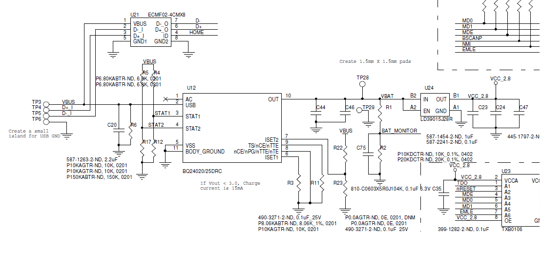
A BQ24020 charger IC is being utilized to charge a 120mAh Li-ion battery with a set charge current of approximately 100mA. The circuit schematic has been provided. The issue encountered is that the STAT1 and STAT2 signals indicate the...
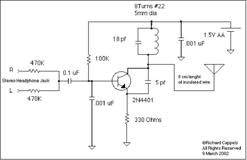
This implementation is adapted to rebroadcast the output of a CD player, television receiver, or radio receiver. I use it so that I can move about the house and listen to my favorite programs without disturbing others. Within the...
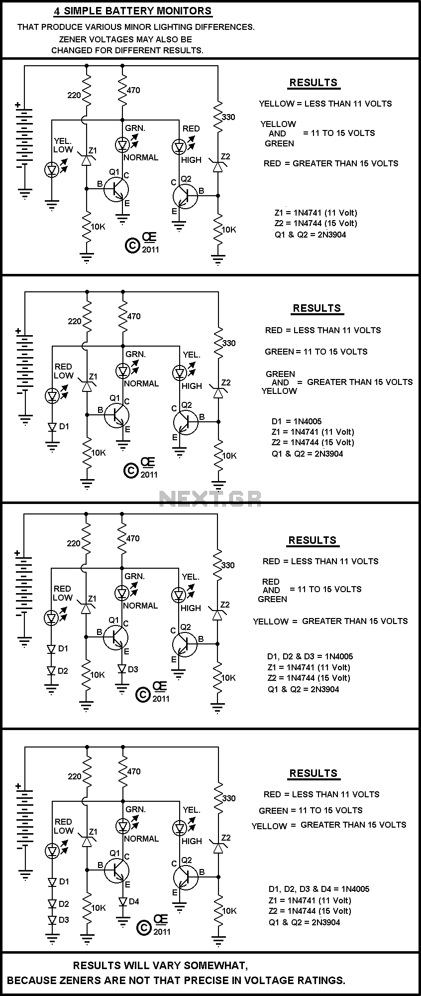
A Very Simple circuit and some Variations. Play with it. All parts are cheap and should be easily obtained. None are very critical. The circuit in question is a basic electronic assembly designed for educational purposes and experimentation. It typically consists...
The charger described in this article can charge packs of 4 to 7 cells with capacities ranging from 600mAh to 2Ah. The charger automatically begins charging when a pack is connected. It charges at a (nearly) constant current (adjustable),...
Traditional guitar amplifier tubes, such as the 12AX7, utilize indirectly-heated cathodes. In this configuration, the heating filament is electrically isolated from the cathode, which emits signal-producing electrons. This design simplifies the circuit significantly, allowing the cathode voltage to be...

This circuit conducts a rapid battery test without requiring an external power supply or costly moving-coil voltmeters. It offers two testing ranges: when switch SW1 is configured as indicated in the circuit diagram, it can evaluate batteries ranging from...
Warning: include(partials/cookie-banner.php): Failed to open stream: Permission denied in /var/www/html/nextgr/view-circuit.php on line 713
Warning: include(): Failed opening 'partials/cookie-banner.php' for inclusion (include_path='.:/usr/share/php') in /var/www/html/nextgr/view-circuit.php on line 713