
Battery SaverCircuit
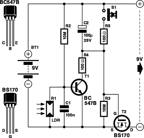
The electronic switch circuit operates on a fundamental principle of using a MOSFET as a low-power switch. The BS170 MOSFET is selected for its efficiency and ability to switch with minimal gate current. The inclusion of capacitor C2 plays a crucial role in timing the operation of the circuit, as it allows the MOSFET to remain in a conducting state for a predetermined duration. The charge and discharge cycle of C2, governed by resistors R3 and R5, ensures that the load remains powered only when necessary, thus conserving battery life.
The light-dependent resistor (LDR) serves as an essential component for ambient light detection. The choice of the FW150 LDR is significant due to its sensitivity and response characteristics, which are suitable for applications where lighting conditions vary. The arrangement of R1 and R2 forms a voltage divider that provides a reference voltage to the base of transistor T1. When the light intensity falls below a certain threshold, T1 activates, leading to a rapid discharge of C2 and effectively shutting off the load.
The overall design of the battery saver circuit allows for versatility in application, making it suitable for various battery-powered devices. The current draw of the circuit in its inactive state is minimal, ensuring that the device remains operational for extended periods without depleting the battery. This circuit can be easily adapted for different voltage levels and load requirements, making it a valuable addition to low-power electronic designs.A small electronic switch that connects a battery to the equipment for a certain amount of time when a push-button is momentarily pressed. And we have also taken the ambient light level into account; when it is dark you won`t be able to read the display so it is only logical to turn the switch off, even if the time delay h
asn`t passed yet. The circuit is quite straightforward. For the actual switch we`re using a well-known MOSFET, the BS170. A MOSFET (T2 in the circuit) used in this configuration doesn`t need a current to make it conduct (just a voltage), which makes the circuit very efficient. When the battery is connected to the battery saver circuit for the first time, capacitor C2 provides the gate of the MOSFET with a positive voltage, which causes T2 to conduct and hence connect the load (on the 9 V output) to the battery (BT1).
C2 is slowly charged up via R3 (i. e. the voltage across C2 increases). This causes the voltage at the gate to drop and eventually it becomes so low that T2 can no longer conduct, removing the supply voltage to the load. In this state the battery saver circuit draws a very small current of about 1 µA. If you now press S1, C2 will discharge and the circuit returns to its initial state, with a new turn-off delay.
Resistor R5 is used to limit the discharge current through the switch to an acceptable level. You only need to hold down the switch for a few hundredths of a second to fully discharge C2. In our prototype, connected between a 9 V battery and a load that drew about 5 mA, the output voltage started to drop after about 26 minutes. After 30 minutes the voltage had dropped to 2. 4 V. You should use a good quality capacitor for C2 (one that has a very low leakage current), otherwise you could have to wait a very long time before the switch turns off!
The ambient light level is detected using an LDR (R1). An LDR is a type of light sensor that reduces in resistance when the light level increases. We recommend that you use an FW150, obtainable from e. g. Conrad as part number 183547-89. When there is too little light its resistance increases and potential divider R1/R2 causes transistor T1 to conduct. T1 then charges up C2 very quickly through R4, which limits the current to a safe level. This stops T2 from conducting and the load is turned off. The choice of value for R2 determines how dark it has to be before T1 starts to conduct. The battery saver circuit can be added to devices that use 6 or 9 volt batteries and which don`t draw more than 100 mA.
The circuit can be built on a piece of experimenter`s board and should be made as compact as possible so that it can be built into the battery powered device. 🔗 External reference
Related Circuits
Schematic and description of a simple and easy-to-build NiCd and NiMH battery charger circuit that is capable of charging multiple NiCd and NiMH batteries. The circuit for the NiCd and NiMH battery charger is designed to be straightforward, allowing for...
This Sealed Lead Acid Battery Charger is designed using the LT3755 DC-DC controller. The LT3755 is a DC-DC controller that operates as a constant-current source and supports a wide input voltage range from 4.5 to 40 volts, providing a...
This circuit is capable of automatically charging 6V and 12V batteries quickly and accurately. A key factor in the successful operation of the circuit is the use of a high-quality transformer (T1) that features excellent insulation and short-circuit resistance. The...
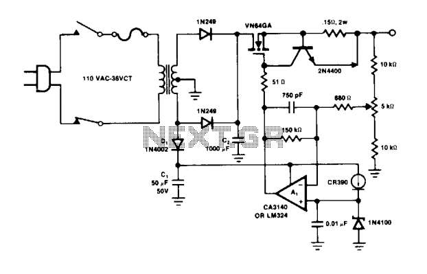
The operational amplifier A1 directly drives the VN64GA with the error signal to control the output voltage. The peak rectifier D1 and capacitor C1 supply the error amplifier A1 and the reference zener. This additional drive voltage must exceed...
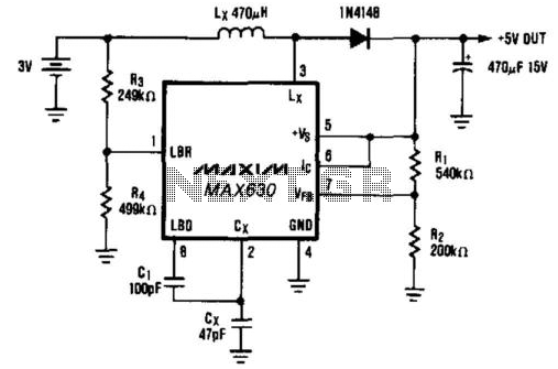
A common power supply requirement involves converting a 2.4- or 3-V battery voltage to a 5-V logic supply. This circuit converts 3 V to 5 V at 40 mA with 85% efficiency. When the IC (pin 6) is driven...
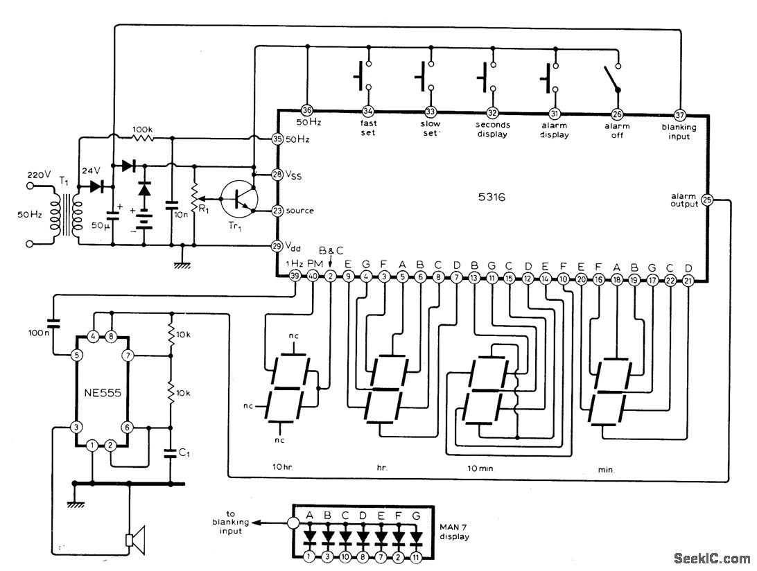
The circuit utilizes the MM5316 alarm-clock integrated circuit (IC), which is originally intended for driving LCD or fluorescent displays. In this implementation, it has been adapted for use with LED display diodes. The system is designed to operate on...
Warning: include(partials/cookie-banner.php): Failed to open stream: Permission denied in /var/www/html/nextgr/view-circuit.php on line 713
Warning: include(): Failed opening 'partials/cookie-banner.php' for inclusion (include_path='.:/usr/share/php') in /var/www/html/nextgr/view-circuit.php on line 713