
bcd counter 7 segment display
The circuit design for a BCD counter that counts from 32 to 84 can be implemented using the CD4510BMS counter IC in conjunction with additional logic gates to achieve the desired counting range. The CD4510 is a presettable binary-coded decimal (BCD) counter that can count up or down based on the configuration of its UP/DN inputs. To enable counting from 32 to 84, the circuit must incorporate additional logic to detect and restrict the counter's output to this specific range.
The detection of the binary values corresponding to 32 (0010 0000) and 84 (0101 0100) can be achieved by utilizing a series of inverters and NAND or NOR gates. For instance, to detect the count of 32, the outputs from specific bits of the counter can be inverted and fed into a multi-input NOR gate. When the counter reaches 32, all inputs to the NOR gate will be low, resulting in a high output, signaling that the count of 32 has been reached. A similar approach can be applied to detect the count of 84, where the relevant bits are monitored, and their states are used to determine when the counter has reached this upper limit.
The circuit should also include debouncing mechanisms for the clock pulse input to ensure that the counter registers each pulse correctly, preventing any missed counts. Capacitors (100 nF) should be placed across the power supply lines of the counter ICs to filter noise and stabilize the operation. The Load, A, B, C, and D inputs of the counter should be grounded to ensure proper functionality, and the UP/DN inputs should be connected to a positive voltage (e.g., +9 volts) to enable counting in the upward direction.
This design requires careful consideration of the connections and logic gate configurations to ensure that the counter operates correctly within the specified range. Testing and validation of the circuit should be conducted to confirm that the counting sequence functions as intended, from 32 to 84 and then looping back to 32.I`m doing this lab BCD COUNTER and 7 SEGMENT DISPLAY and im using CD4510BMS presettable BCD Up/Down Counter. I was able to do the counting from 00-99 but i can`t figure out the counting from 32-84. Do i need another gate for this operation Okay, sorry about that. I need to start it from 32-84 and around again. Instead of starting 00-99, i need to advanced the count and shorten it too. For the schematic i dont have any scanner, so im not able to show it to you. If you know function similar from what my lab does, can you please send it to me ah ok. thats what im doin right now. so what really specific gate do i need to use to make it count from 32-84 im using nand gate right now im just figuring out what are the connections. ah ok. thats what im doin right now. so what really specific gate do i need to use to make it count from 32-84 im using nand gate right now im just figuring out what are the connections.
For count 32 you must detect the binary count of 0011, 0010 from your counter. For 84 you must detect binary count 1000, 0100. You can do that with a series of INVERTER and NAND gates, or INVERTER and NOR gates. It depends upon the polarity output you require when you detect the number. For example, to detect 32 with a logic high output, you could put inverters on bit 2, bit 5, and bit 6, and connect their outputs, along with the other 5, to an 8-input NOR gate. The output of the NOR gate will go high, when count 32 is detected (all NOR inputs low). It will remain low for all other counts. Hello, i`m also doing a 0-99 counter with IC 4511 and 4510. But my circuit wont work. However i press the clock pulse button, the number wont increase. Can anyone upload a schematic using 4510 and 4511 as the counter I`m working on it for more than 5 hours already, still cant get any solution.
"It needs 100 nF capacitors across the counter IC supply line (one for each 4510), the Load, A, B, C & D inputs should be connected to gnd. And, if you want it to count up, connect the UP/DN inputs to +9 Volt. 🔗 External reference
Related Circuits
It was designed for an application in a welding machine: there are lots of bits of machinery which are cylindrical in shape and which are subjected to heavy surface wear. For instance ore crushers, and the idler and roller...
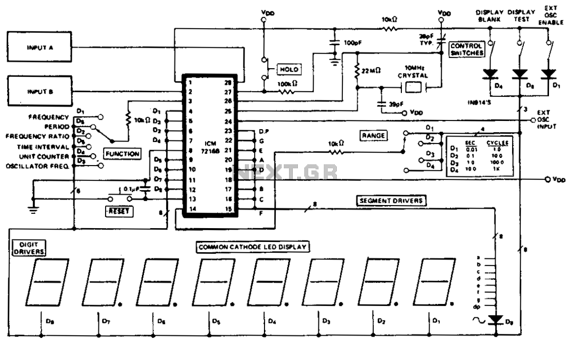
The ICM7216A can be utilized as a complete universal counter with minimal components. This circuit is capable of handling input frequencies of up to 10 MHz at INPUT A and 2 MHz at INPUT B. In cases where the...
This circuit receives a Doppler signal from a radar, amplifies and limits it, and then feeds the frequency into a counter (U4) and a display circuit (DISP1, DISP2, U5, U6). The calibration of the counter is determined by the...
The back-to-back diodes are included because some radios generate high voltage transients when switching bands, which can cause the DFD to lock up, requiring a power cycle to reset. If the power for the backlit display is sourced from...

The circuit is designed to connect in parallel with a telephone, displaying the dialed number using DTMF (Dual Tone Multi-Frequency) signaling. It can also show the number dialed from the receiving party's phone, making it useful for capturing numbers...
You must be able to recognise components such as capacitors, diodes, zeners, transistors and resistors to build a 5x7 Display project. This information is covered in our BASIC ELECTRONICS course and a complete set of circuit symbols can be...