
Bcd-to-analog converter
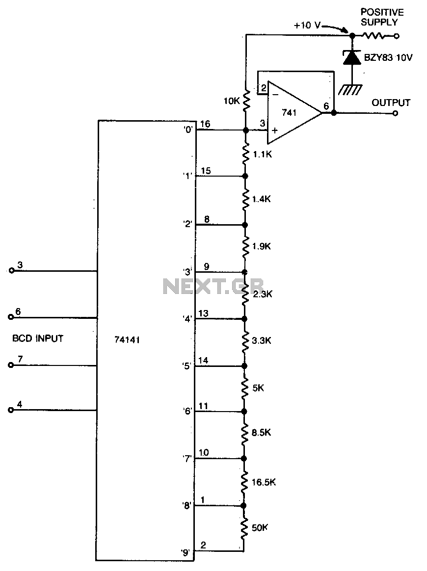
The circuit operates by accepting a four-bit BCD input, which corresponds to decimal values ranging from 0 to 9. The SN74141 is designed to control multiple outputs, each representing a specific voltage level. When a particular BCD code is received, the corresponding output of the SN74141 is activated, grounding the appropriate point in the voltage divider network. This action allows the voltage divider to produce a precise output voltage that matches the decimal value indicated by the BCD input.
The voltage divider consists of a series of resistors that are arranged to provide specific voltage levels at their junctions. The values of these resistors are critical, as they determine the output voltage for each BCD input. The accuracy of the output voltage is contingent upon the tolerance of these resistors; hence, using resistors with low tolerance is advisable for improved precision. Furthermore, a stable reference voltage source is essential for maintaining consistent output voltages across different operating conditions.
To enhance accuracy, the circuit can incorporate adjustable preset resistors within the divider chain. These presets allow for fine-tuning of the output voltages, compensating for any discrepancies caused by resistor tolerances or variations in the reference voltage. Calibration involves setting the presets to achieve the desired output voltage for each BCD input, ensuring that the circuit reliably produces the correct voltage levels.
The inclusion of the SN741 as a buffer serves to isolate the output of the voltage divider from the load, preventing any loading effects that could alter the output voltage. This buffer configuration ensures that the circuit can drive various loads without affecting the voltage levels generated by the divider.
Overall, this circuit provides a straightforward method for converting BCD inputs into corresponding variable voltages, with considerations for accuracy and calibration to ensure reliable performance in practical applications.This circuit will convert four-bit BCD into a variable voltage from 0-9 V in 1 V steps. The SN74141 is a Nixie driver, and has ten open-collector outputs. These are used to ground a selected point in the divider chain determined by the BCD code at the input, and so produce a corresponding voltage at the output. Accuracy of the circuit depends on the tolerance of the resistors and the accuracy of the reference voltage.
However, presets can be used in the divider chain, with correct calibration The 741 is used as a buffer. 🔗 External reference
Related Circuits

The incoming RGB inputs are terminated with resistors R1, R2, and R3, along with potentiometers RV1, RV2, and RV3. These components provide input impedances of approximately 75 ohms. The presets should be adjusted to allow a maximum input of...
This converter is useful when only the serial port on a personal computer is available, while the printer requires a parallel (Centronics) port. It converts a serial signal at 2400 baud into a parallel signal. The TxD line (pin...
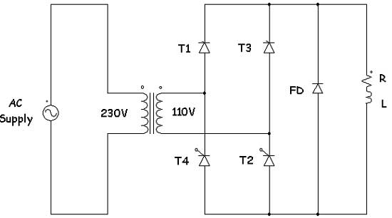
Controlled rectifiers are line-commutated AC to DC power converters that convert a fixed voltage and fixed frequency AC power supply into a variable DC output voltage. The input supply provided to a controlled rectifier is an AC supply with...
A voltage-to-frequency converter (VFC) circuit is depicted in the schematic diagram below. The circuit utilizes a 555 integrated circuit (IC) as the core component for its operation. The voltage-to-frequency converter is a crucial component in various analog and digital...
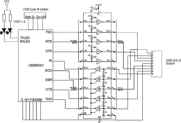
The FT8U232AM requires a small number of external components to produce a device that converts USB to TTL level RS232 signals. All that is needed is a TTL to RS232 converter to provide the 12V RS232 logic levels. The...
This circuit is intended to provide good square waves converting a sine wave picked up from an existing generator. Its main feature consists in the fact that no power source is needed: thus it can be simply connected between...