
introduction to controlled rectifiers with converter

The operation of controlled rectifiers is critical in various applications, including motor speed control, battery charging, and power supplies for industrial equipment. The ability to adjust the DC output voltage and current through phase control provides flexibility in managing power delivery to loads. The choice of thyristors, their ratings, and the design of the triggering circuit are essential for achieving desired performance characteristics, such as efficiency, thermal management, and response time. The use of inductive loads in these circuits aids in smoothing out current variations, thus minimizing ripple and enhancing the stability of the output.
In practical applications, careful consideration must be given to the design of snubber circuits to protect the thyristors from voltage spikes during turn-off, as well as to ensure that the triggering mechanism is reliable and responsive. Additionally, thermal management solutions, such as heat sinks or active cooling, may be required to prevent overheating of the thyristors during prolonged operation. Overall, controlled rectifiers represent a fundamental technology in power electronics, enabling efficient conversion and control of electrical energy.Controlled rectifiers are line commutated ac to dc power converters which are used to convert a fixed voltage, fixed frequency ac power supply into variable dc output voltage. The input supply fed to a controlled rectifier is ac supply at a fixed rms voltage and at a fixed frequency.
We can obtain variable dc output voltage by using controlled rec tifiers. By employing phase controlled thyristors in the controlled rectifier circuits we can obtain variable dc output voltage and variable dc (average) output current by varying the trigger angle (phase angle) at which the thyristors are triggered. We obtain a uni-directional and pulsating load current waveform, which has a specific average value. The thyristors are forward biased during the positive half cycle of input supply and can be turned ON by applying suitable gate trigger pulses at the thyristor gate leads.
The thyristor current and the load current begin to flow once the thyristors are triggered (turned ON) say at ‰t= ±. The load current flows when the thyristors conduct from ‰t= ± to ². The output voltage across the load follows the input supply voltage through the conducting thyristor.
At ‰t= ², when the load current falls to zero, the thyristors turn off due to AC line (natural) commutation. The thyristor remains reverse biased during the negative half cycle of input supply. The type of commutation used in controlled rectifier circuits is referred to AC line commutation or Natural commutation or AC phase commutation.
When the input ac supply voltage reverses and becomes negative during the negative half cycle, the thyristor becomes reverse biased and hence turns off. There are several types of power converters which use ac line commutation. These are referred to as line commutated converters. Half wave controlled rectifier which uses a single thyristor device (which provides output control only in one half cycle of input ac supply, and it provides low dc output).
The circuit diagram of a single phase fully controlled bridge converter is shown in the figure with a highly inductive load and a dc source in the load circuit so that the load current is continuous and ripple free (constant load current operation). The fully controlled bridge converter consists of four thyristors T1, T2, T3 andT4 connected in the form of full wave bridge configuration as shown in the figure.
Each thyristor is controlled and turned on by its gating signal and naturally turns off when a reverse voltage appears across it. During the positive half cycle when the upper line of the transformer secondary winding is at a positive potential with respect to the lower end the thyristors T1 andT2 are forward biased during the time interval ‰t= 0 to.
The thyristors T1 andT2 are triggered simultaneously, the load is connected to the input supply through the conducting thyristors T1 andT2. The output voltage across the load follows the input supply voltage and hence output voltage V0=Vm sin ‰t.
Due to the inductive loadT1 andT2 will continue to conduct beyond ‰t=, even though the input voltage becomes negative. T1 andT2 conduct together during the time period ± to ( + ± ), for a time duration of radians (conduction angle of each thyristor =180 ) During the negative half cycle of input supply voltage for ‰t= to 2, the thyristorsT3 andT4 are forward biased.
T3 andT4 are triggered at ‰t=( + ± ). As soon as the thyristorsT3 andT4 are triggered a reverse voltage appears across the thyristors T1 andT2 and they naturally turn-off and the load current is transferred fromT1 andT2 to the thyristorsT3 andT4. The output voltage across the load follows the supply voltage andV0=-Vm sin ‰t during the time period ‰t=( + ± ) to(2 + ± ).
In the next positive half cycle whenT1 andT2 are triggered, T3 andT4 are reverse biased and they turn-off. The figure shows the waveforms of the input supply voltage, the output load voltage, the constant load current with neglig
🔗 External reference
Related Circuits
This circuit, based on the 555 timer, functions as a voltmeter and an analog-to-digital converter, converting analog input voltage into digital output pulses. The 555 timer is a versatile integrated circuit commonly used for timing, oscillation, and pulse generation applications....

Symmetric 12V to 5V converter power supply. Refer to the designated page for an explanation regarding the associated circuit diagram. The symmetric 12V to 5V converter power supply is designed to efficiently step down a 12V input voltage to a...
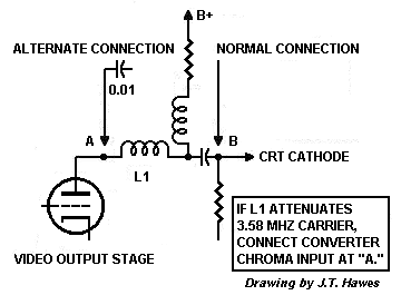
The D 101-2 depends on the television to supply a wide bandwidth video signal. Most black-and-white TVs from 1954 onward contain narrowband intermediate frequency (IF) strips or low-pass filters. A wide passband is a disadvantage because it picks up...
Voltage to frequency conversion is highly beneficial in various applications, such as transmitting temperature measurements using standard voice radio transceivers. This circuit utilizes two CA3130 operational amplifiers, demonstrating satisfactory performance. The linearity of the voltage-frequency transfer is better than...
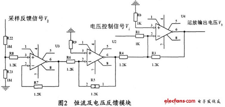
The output current range of the parameter current regulator is limited, and its precision is not high. Connecting the feedback adjustment type output current of the current-stabilized power source in series results in lower efficiency. The steady current source...
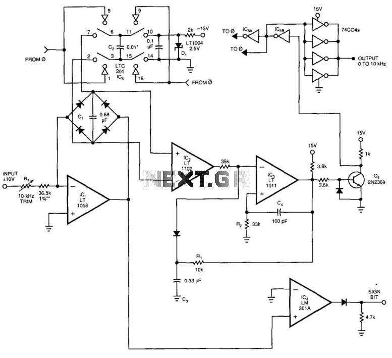
This voltage-to-frequency converter (VFC) accepts bipolar AC inputs. For -10 to +10 V inputs, the converter produces a proportional 0 to 10 kHz output. Linearity is 0.04%, and the temperature coefficient (TC) is approximately 50 ppm/°C. To understand the...