
How to Control Electronic Circuits Using a Computer and the BASIC Programming Language
The described computer system schematic outlines the fundamental architecture of a basic computer. It consists of several key components, each playing a critical role in the overall functionality of the system. The memory unit is responsible for storing both program code and data, ensuring that the CPU has quick access to the information necessary for processing tasks. The storage device, such as a hard drive or SSD, allows for the long-term preservation of user programs and data beyond the immediate session of use.
The graphics interface connects the computer to a display monitor, enabling visual output of processed data, while the communications interface facilitates the exchange of information with other computers or devices over various protocols. The sound generation capability is essential for audio output, enhancing user interaction through auditory feedback.
The user interface devices, including keyboards and mice, provide the necessary means for users to input commands and data into the computer, creating a dynamic interaction between the user and the system.
The Central Processing Unit (CPU) acts as the brain of the computer, executing instructions and managing the flow of data between the various components. The architecture relies on a well-defined bussing system, consisting of an address bus and a data bus, which are crucial for data transfer. The address bus carries the unique identifiers for each component, ensuring that the CPU can communicate with one device at a time without confusion or data collision.
In this setup, the CPU sends out a specific address on the address bus when it needs to communicate with a particular component, such as memory. This action indicates which device should engage with the data bus for either sending or receiving data. Other components remain idle on the data bus unless their address is called, maintaining system integrity and preventing data transfer conflicts.
Overall, this schematic serves as a foundational representation of how a basic computer system operates, highlighting the essential components and their interconnections while emphasizing the importance of organized data management through the use of address and data busses.This paper will guide you through how to do just that. We`ll review a simple computer system and how it works. Then we`ll take a look at the BASIC programming language and the statements that it has that will allow us to `talk` with the external circuitry. Next we`ll take a look at how to `interface` your electronic circuit to a computer so that it works in `harmony` with
the rest of the computer. Lastly, we`ll end with two examples which show simple experiments you can do to practice writing and reading data from your circuit. The figure below shows a simple computer system and its connections. Keep in mind that this is a just a general overview. The circuitry inside a computer can get much more complicated than this but for the purposes of this discussion this general overview will suffice.
The computer above has all the basic components. It has memory for program and data storage, it has a storage device for saving user programs, a graphics interface for connection to a video screen, a communications interface so data can be transferred between it and other computers, a means of generating sounds, user interface devices such as a keyboard, and lastly the brains of the operation the Central Processing Unit or CPU. The first thing that becomes clear is that all these components are connected together using two busses, an address bus and a data bus.
These two busses combined constitute the `bussing system` of the computer and they are the main pipelines for all data transfers inside the computer. Here is how it works. The concept of an address is not new to any us, we each have a street address or a post office box number where mail can be sent to us.
The address uniquely identifies us from our neighbors. This system works the exact same way in a computer system. Each of the components above has a unique address. When the CPU wants to send or receive data from the memory it sends out the unique address for the memory on the address bus. This tells the memory that the data bus is now available to it. Any data put on the data bus from the CPU is for the memory and any data the memory wants to send to the CPU can be put on the data bus.
All the other components in the computer system are attached to the address bus and since the address is not theirs they stay `disconnected` from the data bus so as not to interfere with the transfer of data between the CPU and the addressed device. With the common address bus the CPU can `select` one component at a time for data transfer. This allows the CPU to know exactly where data is being sent to and where it is being received from. The common address bus keeps the system `organized` and keeps multiple components from using the data bus at the same time.
So how many addresses ar 🔗 External reference
Related Circuits
A typical circuit for welding equipment is illustrated in the following circuit diagram. The turn-on delay can be accurately controlled with Potentiometer P2, allowing for effective discharge management. The welding equipment circuit typically incorporates several key components to ensure proper...
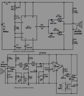
This circuit is straightforward and well-defined. The transmitter operates at 9 volts, while the receiver circuit functions at 5 volts. The transmitter utilizes a 555 timer and two SL100 transistors to perform its function. The receiver incorporates a small...
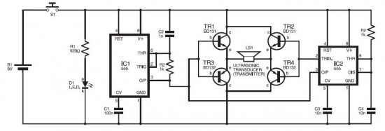
The electronic dog repellent circuit diagram below features a high-output ultrasonic transmitter designed primarily to function as a repeller for dogs and cats. The electronic dog repellent circuit utilizes an ultrasonic transmitter to emit sound waves at frequencies above the...
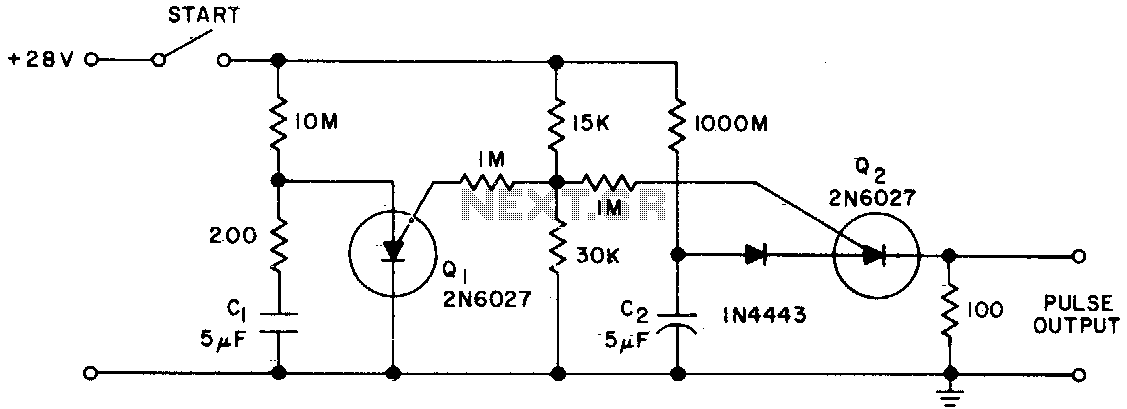
The Programmable Unijunction Transistor (PUT) serves as both a timing element and a sampling oscillator. A low leakage film capacitor is required for capacitor C2 because of the minimal current supplied to it. The Programmable Unijunction Transistor (PUT) is a...

This circuit is designed for lamp dimming and similar applications. It requires only one RC phase lag network. To prevent the hysteresis (or "snap-on") effect, the capacitor is reset to approximately 0 volts at the end of every positive...
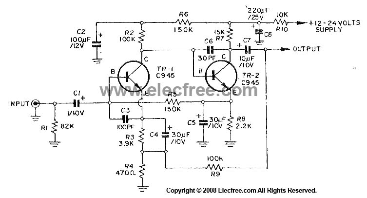
This circuit utilizes three transistors (2SC945, 2C1815, or 2SC828) as the primary components, functioning as a typical low-noise transistor amplifier. It offers a gain of approximately 200 to 300 times and has a frequency response ranging from 50Hz to...