
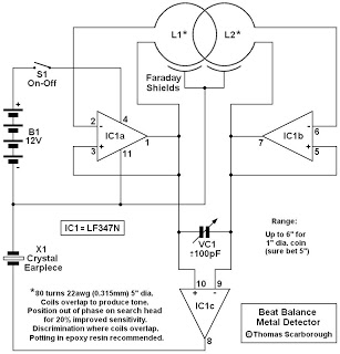
Beat Balance Metal Detector
The metal detector circuit operates on the principle of electromagnetic induction, where a transmitter coil generates an alternating magnetic field. When a metallic object is introduced into this field, eddy currents are induced in the object, which in turn generate their own magnetic field. This interaction modifies the frequency of the oscillators, allowing for the detection of metal objects.
The circuit typically consists of two main components: the transmitter and receiver coils. The transmitter coil is responsible for creating the magnetic field, while the receiver coil detects changes in the field caused by nearby metal objects. The mutual coupling between the coils is crucial, as it allows for the adjustment of the oscillation frequencies. This adjustment leads to a more refined detection capability, enabling the circuit to identify smaller or deeper metallic objects that standard BFO detectors may overlook.
In terms of design, the circuit may include additional components such as resistors, capacitors, and operational amplifiers to enhance signal processing and filtering. The output can be routed to an audio amplifier or a speaker, providing audible feedback to the user when a metal object is detected. The sensitivity and range of the detector can often be tuned by adjusting the values of the components in the circuit, allowing for customization based on the specific application or environment in which the metal detector will be used.
Overall, this metal detector circuit exemplifies a sophisticated application of mutual inductance principles, resulting in a highly effective tool for metal detection with improved performance over conventional designs.Here`s a metal detector circuit that frequencies of the two oscillators are then mixed in similar fashion to BFO, to produce an audible heterodyne. On the surface of it, this design would seem to represent little more than a twinned BFO metal detector.
What makes the metal detector different above all else ( check a simple metal detector ), and si gnificantly increases its range, is that each coil modifies the frequency of the adjacent oscillator through mutual coupling. This introduces the "balance" that is present in an IB metal detector, and boosts sensitivity well beyond that of BFO.
Disclaimer All files are found using legitimate search engine techniques. This site does not and will not condone hacking into sites to create the links it list. We will and do assume that all links found on the search engines we use are obtained in a legal manner and the webmasters are aware of the links listed on the search engines. If you find a URL that belongs to you, and you did not realize that it was "open to the public", please use the report button to notify the blogmaster of your request to remove it or it will remove within 24 hours.
This is not an invitation for webblog haters to spam with requests to remove content they feel that is objectionable and or unacceptable. Proof of URL ownership is required. NOTICE: This Blog Has Already Been Reviewed And Accepted By Blogger. com 🔗 External reference
Related Circuits
One of the simplest methods of metal detecting is through a beat frequency oscillator. The circuit consists of two balanced oscillators: one provides a reference signal, while the other acts as the detector element. The frequency of the reference...
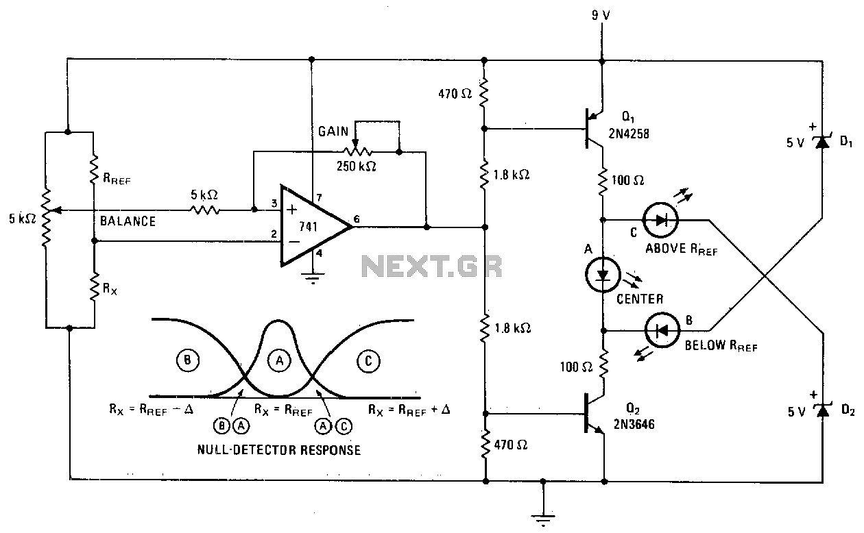
A null detector employs a basic LED readout to indicate whether the test resistor R* is below, equal to, or greater than the reference resistance Rref. When R* equals Rref, the output of the 741 operational amplifier stabilizes at...
This is a basic Cadmium Sulfide (CdS) photocell detector circuit. In this circuit, when light falling on the photocell (PC1) is blocked, its resistance increases, causing the voltage across PC1 to rise. When the voltage exceeds half of the...
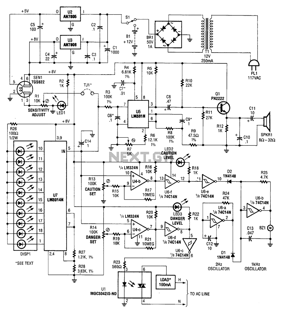
A gas sensor (from Allegro Electronics, Cornwall Bridge, CT06754 Ts GS823) activates in the presence of explosive gas. U5 functions as a voltage-to-frequency converter, with the sensor producing a frequency that is proportional to conductance. The output frequency varies...

A car battery deteriorates with use, typically lasting no more than four years. Initially, its voltage may drop to just 2V when cranking the engine. As the battery ages, its internal impedance increases, leading to a higher voltage drop...
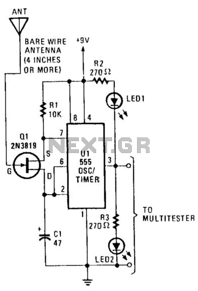
This circuit detects the presence of electrostatic fields by using a Field Effect Transistor (FET) to alter the flash rate of two Light Emitting Diodes (LEDs). The FET is installed in the timing circuit and causes a change in...